This article provides a rigorous guide to calculating transformer impedance percentage for accurate protection settings.
Engineers will find formulas, normative references, tables, and worked examples for practical field application use.
Transformer Impedance Percentage Calculator — Essential Technical Tool
Transformer Impedance Percentage: Technical Fundamentals and Relevance
Transformer impedance percentage (commonly Z%) quantifies the transformer's internal impedance referred to rated quantities. Z% is essential for protection coordination, parallel operation, short‑circuit calculations, and voltage regulation analysis.
Z% defines how much voltage (expressed as a percentage of rated voltage) is required to circulate rated current through a shorted secondary referred to the primary. Accurately calculating Z% and its derived quantities enables reliable fault current estimation and correct breaker selection.
Core Definitions and Standard Formulas
Primary definitions
- Percent Impedance (Z%): the voltage required to produce rated current when the transformer's secondary is short-circuited, expressed as a percentage of rated voltage.
- Per-unit Impedance (Z_pu): Z% divided by 100; a dimensionless representation used for system studies and base conversions.
- Rated current (I_rated): rated load current on a winding, computed from transformer kVA and nominal voltage.
- Short-circuit current (I_sc): prospective fault current limited by the transformer's impedance.
- Z_base (ohms): base impedance for a chosen S_base and V_base, used to convert per-unit impedance to ohms.
Key formulas (presented as plain expressions)
Variable explanations and typical values
- V_sc — short‑circuit voltage magnitude required to circulate rated current, typically measured during factory tests; value depends on winding impedances and leakage.
- V_rated — nominal line voltage on the winding being considered (line-to-line for three-phase). Typical distribution voltages: 480 V, 600 V, 4.16 kV, 13.8 kV.
- S_rated — rated apparent power in VA (e.g., 500 kVA, 150 kVA).
- Z% — typical ranges:
- Small distribution transformers (kVA < 250): 2.5%–8%.
- Medium distribution (250–2000 kVA): 4%–8%.
- Power transformers: 8%–16% depending on design and application.
- Z_base — use matching base S and V to reference impedances for multi-asset networks.
Conversion and Reference Calculations
Computing base impedance and converting to ohms
To convert percent impedance to an absolute resistance/reactance for a given winding base, compute base impedance first.
| Parameter | Symbol | Units | Typical value(s) |
|---|---|---|---|
| Percent impedance | Z% | % | 2.5 – 16 |
| Per‑unit impedance | Z_pu | pu | 0.025 – 0.16 |
| Base impedance | Z_base | Ω | Varies with V^2/S (see table below) |
| Rated current (three‑phase) | I_rated | A | I_rated = S/(√3·V) |
Extensive Typical Values Table
| Transformer kVA | Primary Voltage (kV) | Secondary Voltage (V) | Typical Z% | Typical Z_ohm on secondary base (example) | Notes |
|---|---|---|---|---|---|
| 25 kVA | 4.16 | 240 | 2.5 – 5 | 0.230 – 0.460 (for Z% 2.5–5; Z_base = 240^2/25000 = 2.304 Ω) | Small pole‑mount units often low Z% for voltage regulation concerns. |
| 50 kVA | 4.16 | 480 | 2.5 – 5 | 0.460 – 0.920 (Z_base = 480^2/50000 = 4.608 Ω) | Pad‑mounted and small pad types; manufacturer variation significant. |
| 100 kVA | 13.8 | 480 | 4 – 6 | 0.921 – 1.382 (Z_base = 480^2/100000 = 2.304 Ω) | Common distribution substation secondary; Z% often 4–6%. |
| 150 kVA | 4.16 | 480 | 3.5 – 5.5 | 1.61 – 2.53 (Z_base = 480^2/150000 = 1.536 Ω) | Padmount or small substation units. |
| 500 kVA | 13.8 | 480 | 4 – 7 | 0.4608 × 0.04–0.07 = 0.0184–0.0323 Ω | Higher kVA often slightly higher Z% to limit fault currents. |
| 1000 kVA | 13.8 | 480 | 4.5 – 8 | Calculated per base Z | Utility distribution transformers; design tradeoffs between short‑circuit current and regulation. |
| 10 MVA | 69 | 13.8 kV | 6 – 12 | Large power transformers, Z in this range depending on grid stiffness | Power transformers and transmission applications. |
Practical Calculation Workflow
- Identify rated kVA (S_rated) and nominal voltage for the winding (V_rated).
- Confirm manufacturer specified Z% (from nameplate or factory test report).
- Compute Z_pu = Z% / 100.
- Compute base impedance Z_base = V_rated^2 / S_rated (use consistent units: V and VA).
- Obtain Z_ohm = Z_pu × Z_base.
- Compute rated current I_rated = S_rated / (√3 × V_rated) for three‑phase arrangements.
- Estimate prospective short‑circuit current: I_sc = I_rated / Z_pu.
- Calculate voltage drop at any load: V_drop = V_rated × (I_load / I_rated) × Z_pu.
Worked Examples — Real Cases
Case 1: 500 kVA, 13.8 kV/480 V three‑phase distribution transformer with Z% = 6%
Given
- S_rated = 500 kVA = 500,000 VA
- V_secondary = 480 V (line‑to‑line)
- Z% = 6%
Step 1, per‑unit impedance:
Step 2, rated current on secondary (three‑phase):
I_rated = S_rated / (√3 × V_secondary) = 500000 / (1.732 × 480) ≈ 500000 / 831.38 ≈ 601.6 A
Step 3, base impedance on secondary:
Step 4, transformer impedance in ohms (secondary base):
Step 5, prospective short‑circuit current at rated voltage:
Step 6, voltage drop at 80% rated current:
Interpretation and verification:
- Short‑circuit current ≈ 10 kA on secondary. Use this value for protective device interrupting rating selection, coordination, and bus bar mechanical design checks.
- Voltage drop at 80% load is 4.8% of rated secondary voltage, consistent with Z% influence on regulation.
Case 2: 150 kVA, 4.16 kV/480 V three‑phase pad‑mounted transformer with Z% = 4%
Given
- S_rated = 150 kVA = 150,000 VA
- V_secondary = 480 V
- Z% = 4%
Step 1, per‑unit impedance:
Step 2, rated current on secondary:
Step 3, base impedance on secondary:
Step 4, transformer impedance in ohms:
Step 5, short‑circuit current:
Step 6, voltage drop at full load (100%):
Engineering remarks:
- Z% = 4% gives lower prospective fault current compared with lower Z% but still provides acceptable regulation (4%).
- Use I_sc = 4.51 kA to determine minimum interrupting rating of upstream protective devices and bus/cable mechanical limits.
Additional Example: Multi‑Transformer Parallel Operation Check
Parallel operation requires near‑equal voltage ratios, phase rotation, and compatible percent impedances. For load sharing, percent impedances determine current division inversely proportional to Z_pu.
Consider two identical 1000 kVA transformers connected in parallel, each Z% = 5%. If one transformer had Z% = 4%, the share changes. Current share (approx) is inverse of Z_ohm. This affects thermal loading and protection settings.
Common Practical Considerations and Calculator 'Must Have' Features
Essential calculator capabilities
- Input modes: nameplate Z% or measured V_sc and rated voltage.
- Support for single‑phase and three‑phase bases and conversions.
- Automatic computation of Z_base, Z_ohm, I_rated, I_sc, and voltage drop for any load percentage.
- Option to enter S_base and V_base for system per‑unit studies and transform between bases.
- Clear units and significant‑figure control with unit conversion (kV, V, kVA, A).
- Exportable results and stepwise solution display for documentation, commissioning, and protection coordination reports.
Advanced features for professional use
- Inclusion of X/R ratio influence on asymmetrical fault current and DC offset.
- Integration with short‑circuit calculation engines for multi‑source systems (e.g., system short‑circuit current contribution, motor starting).
- Support for temperature correction and tap changer position effects on Z%.
- Database of typical manufacturer impedances by kVA and product line for default values.
- Provision for measured impedance input (from short‑circuit test data) including separate R and X components.
Normative References and Authoritative Resources
Use recognized standards and authoritative literature when performing transformer impedance calculations and applying results to protection design:
- IEC 60076 series — Power Transformers (general technical rules and testing). See: https://www.iec.ch/standards
- IEEE C57.12.x — IEEE Standard for Distribution Transformers (manufacturer guidance and testing practices). See: https://standards.ieee.org/
- IEEE Std C37.010 — Guide for Application of Current Transformers Used for Protective Relaying Purposes. Relevant for current measurement in fault studies.
- NEMA and CIGRÉ technical reports — guidance on transformer specification and system studies.
- Manufacturer technical manuals (e.g., ABB, Siemens, Schneider Electric) for product‑specific impedance data and factory test reports.
Note: access to full standard texts may require purchase or subscription; refer to standards bodies for authoritative copies.
Common Pitfalls, Accuracy, and Field Measurements
Typical errors and mitigations
- Mismatched bases: Always ensure S_base and V_base are consistent when converting per‑unit impedances.
- Confusion between percent impedance on nameplate (typically given at rated tap position) and in‑service impedance at other tap positions — check tap changer effect.
- Neglecting X/R ratio: peak asymmetrical current may exceed steady‑state I_sc; protectors and mechanical stresses require X/R consideration.
- Using idealized Z% without temperature correction: resistance varies with temperature affecting R contribution; for X this is less sensitive.
- Parallel operation: unequal Z% leads to disproportionate load sharing; ensure within acceptable manufacturer tolerances.
Field measurement and verification best practices
- Perform a short‑circuit test (V_sc) under controlled conditions following relevant standards to derive accurate Z%.
- Record tap position, ambient temperature, and test frequency because they affect results.
- Measure R and X components if possible (using impedance bridge or test set) to obtain X/R for asymmetrical fault studies.
- Document factory test reports and nameplate values; use measured data to validate model assumptions in system studies.
Regulatory and Safety Considerations
- Select protective devices with interrupting ratings above the calculated prospective fault current and with appropriate time‑current characteristic coordination.
- Comply with national electrical codes and utility interconnection requirements when specifying transformer impedance and protection settings.
- Consider mechanical withstand of busbars and cables for calculated fault currents to avoid catastrophic failure.
Appendix: Quick Reference Formula Set
| Quantity | Expression | Use |
|---|---|---|
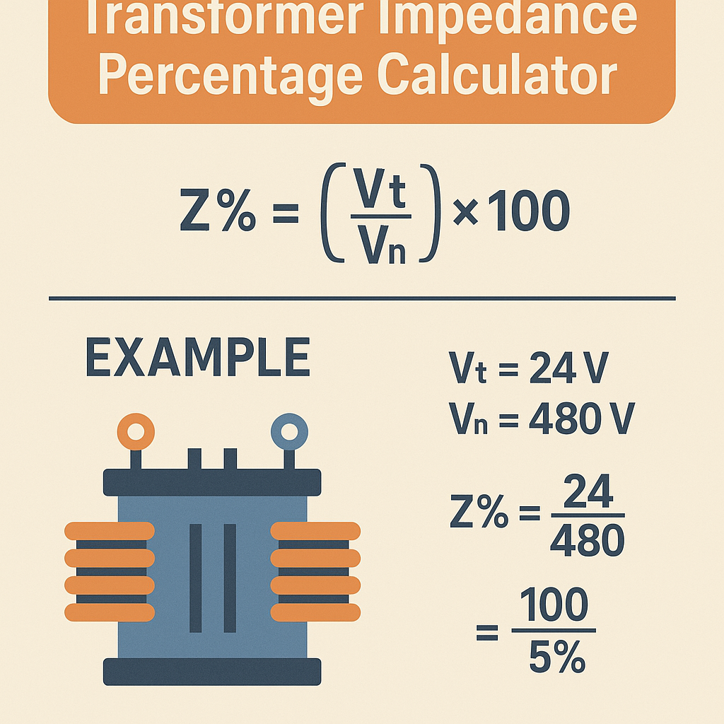
| Percent impedance | Z% = (V_sc / V_rated) × 100 | Direct nameplate or test-derived quantity |
| Per‑unit impedance | Z_pu = Z% / 100 | System studies and base conversions |
| Base impedance | Z_base = V_base^2 / S_base | Converts per‑unit into ohms |
| Transformer impedance (ohms) | Z_ohm = Z_pu × Z_base | Direct use in network calculations |
| Rated current (3‑phase) | I_rated = S_rated / (√3 × V) | Base current for load and fault calculations |
| Short‑circuit current | I_sc = I_rated / Z_pu | Prospective fault current at rated voltage |
| Voltage drop | V_drop_V = V_rated × (I_load / I_rated) × Z_pu | Regulation and load voltage estimation |
Best Practice Checklist for Engineers
- Always confirm Z% from the transformer's nameplate or factory test report before using default values.
- Use consistent units (V in volts, S in VA) and clearly document base values for per‑unit analysis.
- Include X/R ratio in protection and asymmetrical fault calculations.
- Verify tap changer positions—impedance varies with tap settings and affects regulation and fault currents.
- For parallel operation, ensure percent impedance tolerances are within manufacturer recommended limits and phase shift is compatible.
- Use conservative safety margins for protective device selection and mechanical strength assessments.
Further Reading and Resources
- IEC 60076 — Power Transformers: type tests and routine tests guidance (purchase or library access).
- IEEE Std C57.12 series — Distribution transformer specifications and testing guidance (available through IEEE).
- Transformer short-circuit testing and example reports from major manufacturers: ABB (https://www.abb.com), Siemens (https://www.siemens.com), Schneider Electric (https://www.se.com).
- General power systems textbooks for in‑depth system short‑circuit theory and per‑unit methodology, e.g., "Power System Analysis" references.
Final Notes on Implementation
Accurate transformer impedance calculation and verification underpin safe, reliable electrical systems. Implement the calculator features outlined above and follow the presented workflows for consistently reproducible results.
When in doubt, corroborate nameplate data with factory test reports, and, if necessary, perform on‑site verification testing under controlled conditions to validate assumptions used in protection and system studies.