This article provides a precise, technical tool for sizing EGCs for parallel conductors in raceways.
Guidance aligns with NEC 250.122(f), multiple raceways considerations, and practical quick-calculator methodology for design engineers.
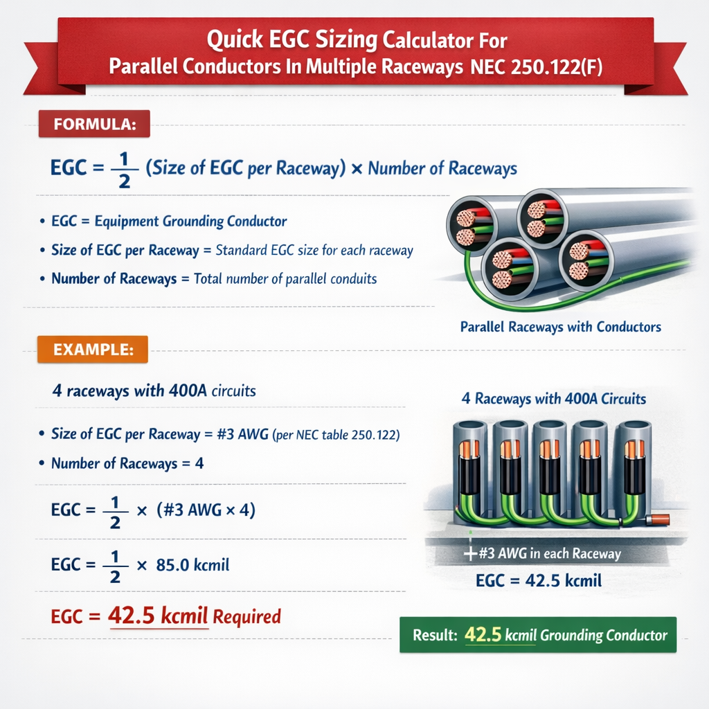
Quick EGC Sizing Calculator for Parallel Conductors in Multiple Raceways (NEC 250.122(F))
Background and scope for quick EGC sizing in parallel installations
This document defines a clear, repeatable method to size equipment grounding conductors (EGCs) when conductors are installed in parallel across multiple raceways. It focuses on practical calculation logic that aligns with NEC requirements (reference to NEC 250.122 and related paragraphs), explains required inputs, gives formulas you can implement in a calculator, and includes worked examples for real-world scenarios.
Regulatory basis and references
NEC 250.122 establishes minimum EGC sizes based on the rating of the overcurrent protective device (OCPD). Paragraphs addressing multiple conductor installations or paralleled conductors (e.g., provisions in 250 series and conductor-paralleling requirements in 310.10 and 310.10(G)) influence how EGCs are implemented for paralleled feeders. Always verify against the latest NEC edition and local amendments.
- Primary authority: NFPA 70 (NEC) — see the official NFPA resource: https://www.nfpa.org/NEC
- Supplementary guidance: IEEE Std 142 (Green Book) for grounding best practices — https://standards.ieee.org/
- International grounding context: IEC 60364 for earthing system principles — https://www.iec.ch/
Key principles for EGC sizing when conductors are paralleled
Principle 1 — Use OCPD rating as the sizing driver
NEC Table 250.122 (or the equivalent table in the current NEC edition) sets the minimum EGC size based on the ampere rating of the OCPD protecting the circuit. The calculator first determines the required EGC size from the OCPD rating.
Principle 2 — Each parallel set needs its own EGC sized per the OCPD
When current-carrying conductors are installed in parallel, each parallel conductor set (i.e., each raceway run that constitutes one share of the parallel assembly) must include an EGC. Each EGC must be sized not smaller than Table 250.122 requires for the OCPD protecting the entire circuit.
Principle 3 — Parallel EGCs can be combined if electrically continuous
If multiple EGCs are installed in parallel and electrically connected at both ends, the effective cross-sectional area is the arithmetic sum of the individual conductor areas. The calculator tests whether the summed area of parallel EGCs meets or exceeds the required single-conductor EGC area from the NEC table.
Data inputs required for the quick calculator
- Overcurrent device rating (OCPD in amperes).
- Material of grounding conductor (copper or aluminum/copper-clad aluminum).
- Number of parallel runs/raceways and number of EGCs per run.
- EGC sizes actually proposed for each run (AWG or metric mm²).
- Whether EGCs are electrically commoned (connected) at both ends.
Formulas and calculation logic (HTML-only expressions)
Core formulas used by the calculator are presented with variable definitions and typical values. These use plain HTML text representations.
3) If multiple parallel EGCs are connected in parallel and electrically continuous: A_total = A_1 + A_2 + ... + A_n
Variable explanations:
- A_i — cross-sectional area of the i-th EGC conductor (mm² or kcmil). Typical values for AWG are provided in a conversion table below.
- A_total — arithmetic sum of the cross-sectional areas of parallel EGC conductors that are electrically interconnected.
- Required_EGC_size — AWG or kcmil size determined from NEC Table 250.122 for the given OCPD.
- lookup() — table lookup function referencing NEC Table 250.122.
Common NEC values: Table 250.122 quick reference
The following table summarizes common Table 250.122 values used in field calculations. Always confirm with the current NEC edition and local amendments.
| OCPD Rating (A) | Minimum EGC (Copper AWG) | Minimum EGC (Aluminum / CCA AWG) |
|---|---|---|
| 15 | 14 | 12 |
| 20 | 12 | 10 |
| 30 | 10 | 8 |
| 60 | 10 | 8 |
| 100 | 8 | 6 |
| 200 | 6 | 4 |
| 300 | 4 | 2 |
| 400 | 3 | 1/0 |
| 500 | 2 | 2/0 |
| 600 | 1 | 3/0 |
| 800 | 1/0 | 4/0 |
| 1000 | 2/0 | 250 kcmil |
Note: This table is a condensed illustrative reference. Always check the official NEC Table 250.122 in the current code cycle.
AWG to cross-sectional area conversion (mm²) for area arithmetic
To compute combined areas when EGCs are paralleled, convert AWG sizes to mm² using the conversion table below. Use mm² for arithmetic addition; if you prefer kcmil, use that consistently.
| AWG / Size | Cross-Sectional Area (mm²) | Notes |
|---|---|---|
| 14 | 2.08 | Common NM branch circuits |
| 12 | 3.31 | 20 A circuits |
| 10 | 5.26 | 30 A circuits |
| 8 | 8.36 | Typically used for 40–55 A |
| 6 | 13.30 | Used for 55–65 A circuits |
| 4 | 21.15 | Large branch feeders |
| 3 | 26.67 | Intermediate large conductors |
| 2 | 33.62 | Heavy feeders |
| 1 | 42.41 | Very large feeders |
| 1/0 | 53.50 | Motor feeders, larger panels |
| 2/0 | 67.40 | Large service conductors |
| 3/0 | 85.00 | Very large service feeders |
| 4/0 | 107.20 | Service and bus conductors |
Calculator algorithm summary (step-by-step)
- Input OCPD rating and conductor material (copper or aluminum).
- Lookup Required_EGC_size from NEC Table 250.122.
- List the number of parallel runs and EGC AWG for each run.
- Convert each EGC AWG to mm² (A_i) using the AWG table.
- If EGCs are connected electrically at both ends, compute A_total = Σ A_i.
- Compare A_total to area(Required_EGC_size). If A_total ≥ area(Required_EGC_size), the parallel combination is acceptable. If not, increase EGC size or add additional parallel paths.
- Document the calculations and include references to the NEC edition used.
Example 1 — Two parallel feeders in separate raceways (complete development)
Scenario: A 400 A service is supplied using two parallel feeders (each conductor set carries half the load), each run in its own raceway. The OCPD protecting the combined feeders is 400 A. Each feeder will include an equipment grounding conductor #6 AWG copper. Verify compliance with NEC Table 250.122.
Step-by-step solution
- OCPD rating = 400 A.
- Lookup Required_EGC_size for 400 A from Table 250.122: Required_EGC_size (copper) = AWG 3 (refer to table above).
- Required EGC area = area(AWG 3) = 26.67 mm² (from conversion table).
- Proposed EGC per run = AWG 6 → area = 13.30 mm².
- There are two parallel EGCs (one in each raceway) electrically commoned at both ends, so compute combined area:
A_total = 13.30 mm² + 13.30 mm² = 26.60 mm².
- Compare A_total to required area:
26.60 mm² (combined) vs 26.67 mm² (required).
The combined area is marginally less by 0.07 mm²; rounding and manufacturer tolerances might make this effectively equal, but per strict compliance the combined area is slightly less. To be conservative, increase one EGC to AWG 4 (21.15 mm²) or use AWG 6 + AWG 4 combination. - Alternative solution: Use two parallel AWG 6 plus additional bonding strap or upsize to AWG 4 EGC in each run. If each EGC is AWG 4 (21.15 mm²) and two are paralleled, A_total = 42.30 mm² which exceeds the required 26.67 mm².
Design note: Many field engineers prefer to size each EGC individually to meet Table 250.122 (i.e., each run contains at least the table-required EGC). If this approach is applied here, each run would need AWG 3 EGC which may be impractical; paralleled smaller EGCs are acceptable provided the combined cross-sectional area equals or exceeds the table requirement and the EGCs are electrically continuous.
Example 2 — Three parallel raceways feeding a large motor starter
Scenario: A motor starter has an OCPD rating of 600 A. Feeders are installed as three parallel raceways, each with an EGC proposed as AWG 1 copper. Confirm whether the three EGCs paralleled meet NEC requirements.
Step-by-step solution
- OCPD rating = 600 A.
- Required EGC_size for 600 A (copper) = AWG 1 (per Table 250.122).
- Required area = area(AWG 1) = 42.41 mm².
- Proposed EGC per run = AWG 1 → area per run = 42.41 mm².
- Three parallel EGCs combined: A_total = 42.41 + 42.41 + 42.41 = 127.23 mm².
- Compare A_total to required area:
127.23 mm² (combined) ≥ 42.41 mm² (required) — clearly compliant.
- Design commentary: In this case, each EGC already equals the required size, so paralleled combination is more than adequate. The calculator should accept the proposal immediately.
Edge conditions and practical considerations
- Continuity: Parallel EGCs must be electrically continuous and connected at both supply and load ends to be treated as parallel paths for area summation.
- Terminations: Ensure mechanical and electrochemical compatibility of multiple terminations; each termination must have required clamping and corrosion control.
- Material differences: Do not sum copper and aluminum EGC areas directly without appropriate conversion. Convert to a common unit (mm² or kcmil) and consider conductivity differences if assessing impedance or fault current capacity.
- Bonding jumpers: Where raceways are metallic and bonded, evaluate whether raceway metal constitutes an effective grounding path and whether code allows reliance solely on conduit for the EGC.
- Voltage and fault current: The EGC must carry fault current until the OCPD operates. Sizing by area per NEC Table 250.122 is a minimum; ensure conductor ampacity, thermal limits, and mechanical strength are acceptable.
Implementing the quick-calculator (programmer notes)
Inputs and UI elements
- Numeric field: OCPD rating (A).
- Dropdown: Conductor material (Copper / Aluminum / CCA).
- Repeatable block: For each parallel run, input EGC AWG (or mm²) and checkbox whether EGC is bonded at both ends.
- Option: Allow the user to select whether to compare per-run EGCs individually to the table requirement or to allow summation of paralleled EGCs.
Calculation steps (back-end)
- Map OCPD to Required_EGC_size via Table_250_122 data structure.
- For each run, convert AWG to mm² using a static lookup.
- If all runs marked "bonded both ends" → sum areas; else require each run to individually meet Table requirement (fail otherwise).
- Output pass/fail with recommended corrective actions (upsizing, add additional parallel EGCs, change material).
Troubleshooting common site conditions
- If combined area is marginally below requirement, consider:
- Upsizing one EGC by one AWG size (e.g., from AWG 6 to AWG 4) and retesting.
- Adding a bonding jumper sized per Table 250.122 and physically connecting the EGCs to increase combined capacity.
- If raceway fill or physical constraints limit EGC sizes, consider consolidating conductors in a single, larger raceway or using alternate routing with acceptable mechanical protection.
Record-keeping and labeling
For AHJ review and future maintenance, include the following documentation with the calculation output:
- NEC edition used and citation for Table 250.122.
- List of all parallel runs and EGC sizes (AWG and converted mm²).
- Combined area computation and compliance check.
- Photos or diagrams showing bonding terminations and continuity connections.
References and external authority links
- NFPA 70, National Electrical Code (NEC) — main resource and code edition identification: https://www.nfpa.org/NEC
- NEC Table 250.122 — consult current code edition for the official table: https://www.nfpa.org/NEC/About-the-NEC (direct table access requires the published code book)
- IEEE Std 142 (Green Book) — grounding and bonding guidance: https://standards.ieee.org/standard/142-2007.html
- IEC 60364 series — electrical installations of buildings (for international earthing practices): https://www.iec.ch/
Best-practice checklist for field engineers
- Confirm the OCPD protecting the circuit and select the corresponding EGC size from the current NEC Table 250.122.
- Document the number of parallel raceways and EGCs; verify mechanical terminations will be done per manufacturer guidance.
- Convert EGC sizes to a common cross-sectional area unit and verify combined area meets or exceeds the required area.
- Ensure EGCs are electrically continuous and properly bonded at both ends if relying on combined area.
- Submit calculations and photos to the AHJ for acceptance where parallel EGCs are used as a compliance method.
Summary of the calculator’s outputs and actionable recommendations
The quick EGC sizing calculator yields a clear pass/fail determination. If the proposed EGC configuration fails, recommendations typically include:
- Upsize one or more parallel EGCs to reach the required combined area.
- Add additional parallel EGC conductors and bond them properly.
- Re-route conductors into fewer, larger raceways so individual EGCs can meet Table 250.122 per run.
Implementing a calculator that follows the logic and formulas above will save design time, reduce on-site surprises, and produce code-compliant documentation for permitting and inspection. Always validate outputs against the latest NEC edition and consult the AHJ for jurisdictional acceptance of parallel EGC summation methods.