This technical article explains neutral-to-ground bond validation methods for service, SDS, and subpanels quickly safely.
Designed for engineers and electricians, it provides tests, formulas, examples, and code references practical guidance.
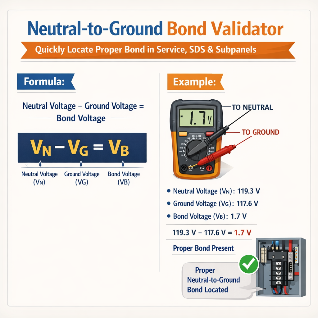
Neutral-to-Ground Bond Validator — Locate Correct Bond in Service, Main & Subpanels
Overview of Neutral-to-Ground Bond Validation
Neutral-to-ground bonding at the service point is a fundamental safety requirement in low-voltage AC power distribution. A proper bond transfers fault current to the grounding system, ensures overcurrent device operation, and stabilizes system voltages during abnormal conditions. Validation means verifying the bond exists at the correct location, is electrically continuous, and meets functional resistance and installation criteria defined by codes and industry best practices.This article presents validated measurement techniques, accepted thresholds, instrumentation selection, and diagnostic workflows to quickly locate the neutral-to-ground bond in service equipment, service disconnect (SDS), and subpanels. It includes prescriptive tables, HTML-based formulas with variable explanations and typical values, and fully worked examples showing step-by-step measurement, calculation, and corrective actions.Codes, Standards, and Authority References
Neutral-to-ground bonding and grounding requirements are documented across multiple authoritative standards and codes. Key references include:- NFPA 70 — National Electrical Code (NEC): requirements for service bonding, grounding electrode conductor (GEC), and grounded conductor connection at service disconnect. See NFPA 70 chapters related to grounding and bonding.
- IEEE Std 142 — Grounding of Industrial and Commercial Power Systems (Green Book): practical grounding system design, bonding practices, and testing methods.
- NECA/NFPA/ANSI and NETA ATS — Standards for acceptance testing of electrical power equipment, including ground continuity and bond testing.
- UL 467 — Standard for grounding and bonding equipment.
- OSHA 29 CFR 1910 — General requirements addressing electrical safety-related work practices and bonding when applicable.
- NFPA 70 (NEC): https://www.nfpa.org/
- IEEE Std 142 overview: https://standards.ieee.org/standard/142-2007.html
- NETA (acceptance testing): https://www.netaworld.org/
- UL 467 summary: https://www.ul.com/
- OSHA electrical safety: https://www.osha.gov/electrical
Definitions and Typical System Components
Key terms
- Neutral (grounded conductor): The conductor normally connected to the system center point or grounded point of the system.
- Equipment Grounding Conductor (EGC): Conductors that connect non-current-carrying metal parts of equipment to the grounding electrode system or service equipment.
- Neutral-to-Ground Bond: The intentional connection between the neutral (grounded conductor) and the equipment-grounding system at the service disconnect or main bonding jumper location.
- Service Disconnect / SDS: Service Disconnect Switch (SDS) generally denotes the main service device where the neutral-to-ground bond should occur for typical premises installations.
- Subpanel (distribution panel): Downstream panel where the neutral must be isolated from equipment grounding conductors.
Principles of Measurement and Acceptance Criteria
Validating bond location and integrity requires a combination of visual inspection and electrical tests. Acceptable outcomes vary by intent (continuity, impedance, or operational fault current), but the following principles guide testing:- Continuity test: Verifies metallic connection between neutral bus and grounding electrode conductor or frame. Typical target: very low ohms, ideally < 1.0 Ω and commonly < 0.1 Ω for short conductive paths.
- Bond impedance test: Measures impedance of the bond path under simulated fault conditions, often using low-frequency injection or clamp-on fault current meters. Lower impedance yields higher fault current and faster protective device operation.
- Operational fault current calculation: Confirms the bond location provides sufficient current return path to operate overcurrent protective devices (OCPDs) within required clearing times per equipment ratings.
Instruments and Tools for Bond Validation
- Digital low-resistance ohmmeter (DLRO) or micro-ohmmeter for milli-ohm-to-volt-level continuity measurements.
- Clamp-on leakage/ground resistance tester capable of measuring AC current and ground loop resistance without disconnecting conductors.
- Low-frequency impedance tester or loop impedance tester to measure prospective fault current and loop impedance.
- Insulation resistance tester (megger) to check for unintended connections between neutral and ground where isolation is required (subpanels).
- Standard hand tools, torque wrenches, and bolted joint inspection tools for mechanical verification.
Recommended Acceptance Thresholds and Common Values
Below are practical target ranges used by engineers and testing professionals for neutral-to-ground bonding and related measurements. Use them as guidance; always confirm with AHJ, utility, and project specifications.| Measurement | Typical Target | Notes |
|---|---|---|
| Neutral-to-Ground continuity (short internal path) | < 0.1 Ω preferable; < 1.0 Ω acceptable in many field scenarios | Measure with DLRO; low values ensure minimal voltage rise of enclosure during fault. |
| Equipment grounding conductor continuous check | Near zero ohms across conductor length | Continuity test through connectors; bolted joints should show low, stable readings. |
| Grounding electrode system resistance to earth | < 25 Ω common utility target; < 5 Ω preferred where possible | NEC does not mandate 25 Ω but many utilities require it for lightning/communications. |
| Loop impedance for circuit protective device operation | Such that I_fault × Time clears per OCPD curve | Measured loop Z should yield sufficient prospective fault current to trip breakers. |
| Insulation resistance between neutral and ground (isolated subpanel) | > 1 MΩ typical for low-voltage systems | Higher values desirable; failure indicates unintended bond or moisture contamination. |
Formulas and Variable Explanations
All formulas are presented using plain HTML characters. After each formula, variables are explained and typical values are provided.Ohm's Law for voltage drop or fault voltage: V = I × R
- V — Voltage (volts). Typical service: 120 V (single-phase), 208 V, 240 V, or 480 V (three-phase).
- I — Current (amperes). Typical prospective fault currents vary widely; calculations shown in examples.
- R — Resistance (Ω). Bond path resistance typically small, < 1 Ω for connections; grounding electrode system higher.
Prospective fault current approximation: I_fault = V_system / Z_loop
- I_fault — Prospective fault current (A).
- V_system — Phase-to-ground voltage (V). For a 120/240 V single-phase system, V_phase-to-ground = 120 V.
- Z_loop — Loop impedance (Ω). Sum of conductor, connection, and source impedances.
Series bond resistance total: R_total = R_bond + R_conductors + R_connections
- R_bond — Resistance of the neutral-to-ground bonding jumper or connection (Ω).
- R_conductors — Resistance of neutral and grounding conductors in the fault loop (Ω).
- R_connections — Resistance of bolted/lugged connections (Ω).
Time-current verification using basic trip approximation: t_trip approximated from breaker characteristic tables based on I_fault.
- Use manufacturer OCPD curves to determine clearing time versus multiple of rated current.
Visual Inspection Checklist Before Electrical Testing
Perform these inspections to ensure safe testing and to find obvious bond locations:- Confirm main service disconnect location and whether neutral and ground terminals are in the same enclosure.
- Look for a main bonding jumper connecting neutral bus to enclosure or GEC lug.
- Trace the grounding electrode conductor (GEC) from the service equipment to electrodes (ground rods, Ufer, etc.).
- Check subpanels: verify neutral bus isolated from panel chassis (insulators, isolated mounting hardware) and EGC bonded to chassis.
- Note presence of multi-wire branch circuits (MWBC) and whether neutrals are shared—incorrect neutral-ground ties may be present downstream.
Step-by-Step Procedures to Locate the Bond
Below are procedures tuned for speed and safety when locating neutral-to-ground bonds in service equipment, SDS, and subpanels.Procedure A — Service/Main Bond Locator
- De-energize circuits if possible. If de-energizing is not practical, use non-contact voltage detection and lockout/tagout per site procedures.
- Visually inspect service equipment for main bonding jumper and GEC connections.
- Measure continuity between neutral bus and equipment enclosure with DLRO. Expected: very low ohms if bonded at service.
- Measure continuity between neutral bus and grounding electrode conductor at the electrode lug. Again, expect low ohms with direct bond.
- If continuity is high or intermittent, measure individual connections (neutral lug, bonding jumper, GEC) to isolate the high-resistance element.
- Document measured resistances and compare to expected thresholds. If resistance is higher than acceptable, tighten lugs to specified torque and retest.
Procedure B — SDS (Service Disconnect Switch) Specifics
SDS commonly indicates the main service disconnect switch assembly. If service equipment and SDS are distinct, repeat Procedure A at SDS:- Confirm SDS is the disconnect recognized as the service disconnect by utility or meter arrangement.
- Verify neutral-to-ground bond is present in SDS unless service structure dictates bond at meter or another enclosure as permitted by NEC and AHJ.
- Measure loop impedance from a representative load feeder to SDS to evaluate prospective fault current.
Procedure C — Subpanel Verification (Isolated Neutral)
- Ensure power is de-energized prior to removing neutral or ground connections where practical.
- Inspect subpanel layout: Neutral bus should be isolated from panel chassis using insulators; EGC must be connected to panel chassis ground bus.
- Measure insulation resistance between neutral bus and panel chassis using a megger. Typical acceptable value > 1 MΩ.
- Measure continuity between neutral bus and grounding electrode/ground conductor; proper subpanel should show open or very high resistance (no bond).
- If an unintended bond exists (neutral bonded to chassis), trace upstream panels or improper jumper installations to remove the bond at the subpanel and relocate bonding to service equipment.
Common Torque and Conductor Size Table
| Conductor Size (AWG/kcmil) | Common Application | Typical Bond Jumper Size | Recommended Lug Torque (lb-ft) |
|---|---|---|---|
| 14 AWG | Branch circuit | 14 AWG | 10–15 in-lb (0.83–1.25 lb-ft) |
| 8 AWG | Small feeders | 8 AWG | 20–30 in-lb (1.67–2.5 lb-ft) |
| 4 AWG | Feeder service | 4 AWG | 40–60 in-lb (3.33–5 lb-ft) |
| 2/0 AWG | Service equipment | 2/0 AWG bonding jumper often required per NEC | 150–250 in-lb (12.5–20.8 lb-ft) |
| 350 kcmil | Large services | 350 kcmil bus or parallel bonding | Refer to manufacturer torque chart |
Detailed Worked Examples
At least two real-world scenarios are provided with measurements, calculations, and corrective actions.Example 1 — Locate Bond in Residential Service Panel
Situation: A single-family home with a 200 A main service panel feeding several subpanels. Owner reports nuisance breaker trips and neutral conductor overheating suspicion in a subpanel. Objective: Verify neutral-to-ground bond is at main service only; confirm subpanel neutrals are isolated.Step-by-step:- Visual inspection: Open main panel cover (de-energized by contacting utility if required). Identify neutral bus, check for main bonding jumper connecting neutral bus to enclosure. Find a bolted jumper labeled "Main Bond". Photodocument location.
- Continuity test: With power off and all breakers open, use a DLRO to measure resistance between neutral bus and panel enclosure. Measured R_ng = 0.015 Ω (15 mΩ). Interpretation: Very low resistance indicating solid bond at main panel. Acceptable.
- Subpanel check: At the subpanel, visually inspect neutral bus; find neutral bus bolted to enclosure with a bonding screw (improper). This indicates an unintended neutral-to-ground connection at subpanel.
- Isolation verification: With megger, measure insulation resistance between neutral bus and chassis: R_ir = 5 kΩ (indicates intermittent bonding/poor contact). However physical bond screw indicates direct connection when screw is present. Confirm by removing bonding screw and re-measuring; R_ir > 1 MΩ after screw removal. Corrective action: Remove bonding screw permanently; install insulated neutral bus standoffs. Re-tighten all neutral lugs to torque spec and retest continuity between neutral and ground — should read open or very high resistance.
- Final verification: Energize and measure neutral conductor temperature under typical load (thermal imaging) and confirm normal range. Test loop impedance from a representative branch circuit to main service: Z_loop = 0.05 Ω. Calculate prospective fault current: I_fault = 120 V / 0.05 Ω = 2400 A. Result: Sufficient to trip branch breakers in time. Document and report remediation.
- Root cause: Installer had left a bonding screw in subpanel, creating neutral-ground bond downstream causing parallel neutral paths and possible neutral currents on grounding conductors.
- Fix: Removed bond at subpanel and re-established single bonding point at service. Re-torqued connections and confirmed low-resistance bond at main service.
Example 2 — Industrial SDS and Multiple Service Sections
Situation: A small industrial facility with a service disconnect switch (SDS) located in a weatherproof enclosure outside the building; a meter and fused disconnect were upstream. Inside, a service distribution section (SDS) feeds several motor control centers (MCCs). Operators reported grounding faults and a ground-fault protection relay nuisance trip.Objective: Locate the effective neutral-to-ground bond, measure loop impedance to MCCs, and calculate expected fault currents to determine if relay settings are correct.Step-by-step:- Documentation review: Review single-line diagrams and equipment labels. Identify utility meter, SDS outside, and a main service distribution (enclosed) inside labeled "service disconnect." AHJ and utility confirmed the bonding permitted at the main interior SDS.
- Visual inspection: At indoor SDS, find a heavy copper main bonding jumper from neutral bus to panel enclosure, and GEC to ground rods. Outside SDS had no bond — confirms interior SDS is main bonding location.
- Measure bond continuity: DLRO measurement between neutral bus and enclosure R_bond = 0.02 Ω (20 mΩ). Good bond.
- Measure loop impedance to an MCC feeder: Using loop impedance tester at MCC feeder breaker, measured Z_loop = 0.008 Ω (8 mΩ). This low loop impedance because of large copper conductors suggests high prospective fault current.
- Calculate prospective fault current at MCC feeder where V_phase-to-ground = 480 V (three-phase delta with ground or derived system). Approximate using worst single-phase-to-ground voltage for grounded systems; conservatively use 277 V if Y-system. For this example use phase-to-phase 480 V converted for single line approximate: I_fault ≈ 480 V / 0.008 Ω = 60,000 A. Interpret using manufacturer OCPD curve: The main breaker is 800 A, long-time delay characteristics allow high initial peaks; confirm whether relay settings and equipment interrupting ratings accommodate calculated fault current.
- If relay tripping undesired: Evaluate grounding system for resonance, check for CT saturation, verify relay ground-fault pickup and time delay; ensure bond impedance is not too high (would reduce fault current) if tripping is too slow, or if too sensitive, tune settings according to NETA/IEEE guidance.
- Finding: Bond location confirmed at indoor SDS; loop impedance very low as expected for large conductors, yielding high prospective fault current. Ground-fault protection adjusted for expected fault levels. No physical correction to bond needed.
- Recommendation: Maintain documentation, periodic DLRO tests on large connections, and verify relay coordination against measured prospective fault currents.
Troubleshooting High Bond Resistance or Missing Bond
If continuity or loop tests indicate unexpectedly high resistance or no bond, follow this diagnostic flow:- Re-verify instrument calibration and test leads. Use known reference to confirm measurement accuracy.
- Check mechanical connections: loose lugs, corrosion, paint or oxidation at bonding locations are common causes.
- Inspect GEC path and electrodes; corrosion or breaks can increase path resistance even though local bond may be low.
- Measure individual segment resistances: neutral lug to bus, bus to bonding jumper, bonding jumper to enclosure, GEC to electrode. Narrow down high-resistance segment.
- If high resistance persists at bolted joints, perform corrective tightening to manufacturer torque and re-measure. If resistance remains high, remove and clean contact surfaces and reassemble with conductive anti-oxidant compound if appropriate per manufacturer guidance.
- If bond is missing entirely, install main bonding jumper sized per NEC and project specs. Ensure AHJ acceptance for any modifications.
Safety, Lockout/Tagout, and Personnel Protection
Testing and remedial actions on live service equipment are hazardous. Follow these safety requirements:- Use lockout/tagout procedures when possible. Coordinate with utility when de-energization of service asset is required.
- Where live testing is necessary, use proper PPE (arc-rated clothing, insulated gloves, face protection) and maintain safe approach boundaries.
- Qualified person only: All measurements on service and distribution equipment must be performed by trained and qualified electrical personnel per OSHA and NFPA 70E standards.
- Document all tests and corrective actions for future reference and AHJ review.
Data Logging and Reporting for AHJ and Stakeholders
A good validation report contains:- Test instruments used and calibration certificates.
- Visual inspection photos and drawings identifying bond location(s).
- Measured values with timestamps: continuity, loop impedance, insulation resistance, bond torque values.
- Calculations for prospective fault current and trip time justification referencing OCPD curves.
- Corrective actions performed and verification retests.
- Sign-off by qualified tester and responsible engineer.
Additional Practical Tables: Instrument Ranges and Common Measurements
| Instrument | Typical Range | Recommended Use |
|---|---|---|
| DLRO (micro-ohm meter) | 1 μΩ – 2 kΩ | Measure bolted joint and bond continuity to milli-ohm precision. |
| Loop impedance tester | 0.001 Ω – 10 Ω | Measure circuit loop impedance and estimate prospective fault current. |
| Clamp-on ground resistance tester | 0.01 Ω – 10 kΩ | Measure ground conductor resistance without disconnecting; useful on GEC loops. |
| Megger (insulation tester) | 100 kΩ – 10 GΩ | Insulation resistance between conductors and between neutral and ground where isolation required. |
Best Practices and Final Observations
- Always maintain a single point of neutral-to-ground bond in typical premises wiring: usually at the service disconnect or at the supply transformer neutral as required.
- Document bond locations and any permitted exceptions per NEC and AHJ to simplify future troubleshooting.
- Perform periodic verification of bond integrity especially after service work, renovations, or storm events that might disturb bonding hardware or electrodes.
- Use conservative acceptance criteria for continuity (< 0.1 Ω when practical) and always confirm functional performance via loop impedance and fault current calculations.
Normative References and Further Reading
- NFPA 70, National Electrical Code (NEC) — grounding and bonding chapters. https://www.nfpa.org/
- IEEE Std 142, Grounding of Industrial and Commercial Power Systems. https://standards.ieee.org/
- NETA ATS, Standard for Acceptance Testing Specifications for Electrical Power Equipment and Systems. https://www.netaworld.org/
- UL 467, Grounding and Bonding Equipment Standard. https://www.ul.com/
- OSHA Electrical Safety and regulations. https://www.osha.gov/electrical