This article explains NEC 220.82 optional method for rapid dwelling unit service calculations and design.
Practical formulas, examples, tables, and references enable engineers to compute loads quickly and accurately safely.
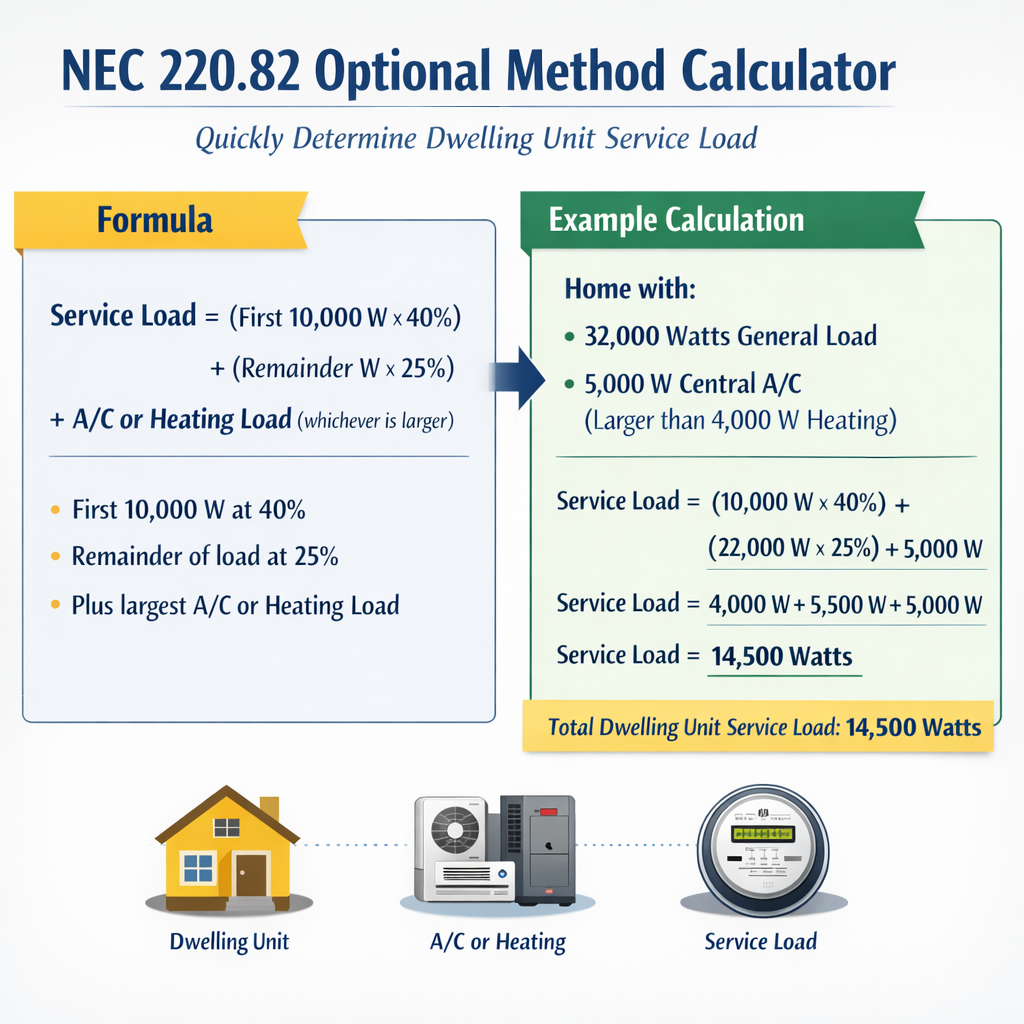
NEC 220.82 Optional Method Calculator – Dwelling Unit Service Load and Recommended Service Rating
Method Overview and Applicability
NEC 220.82 provides an optional method to determine service and feeder loads for dwelling units by applying demand factors to aggregated connected loads. Use this method when the installation conditions match the code provisions and you have identified all connected loads per dwelling unit. Always confirm the applicable NEC edition and local amendments before final design.
What the Optional Method Achieves
- Reduces conservative summation of nameplate ratings by applying permitted demand factors.
- Allows sizing of service conductors and main overcurrent devices for residential services more realistically.
- Requires identification of load groups: general lighting and receptacles, small-appliance circuits, laundry circuits, fixed appliances (ranges, dryers, water heaters), and heating/cooling equipment.
Step-by-Step Calculation Workflow
- Collect nameplate and design data for every dwelling unit (area, lighting, small-appliance circuits, laundry, fixed appliances, HVAC).
- Compute connected VA per unit for each load category using typical VA assumptions or actual nameplate values.
- Group loads according to NEC 220.82 definitions (which loads are subject to demand factors and which are calculated at 100%).
- Apply the NEC Table 220.82 demand factors (or the edition-specific table) to aggregate loads when calculating multi-unit service or feeder demand.
- Perform voltage and power factor adjustments if required, and convert total VA to amps for conductor and overcurrent sizing.
- Verify results against other applicable NEC sections (e.g., 220.61 and 220.83 for ranges, dryers, fixed appliances) and local amendments.
Formulas and Variable Definitions
All formulas are presented as plain HTML expressions. Each variable is explained and common typical values are given after the formula.
Where:
- LightingVA = GeneralLightingArea × VAperft2
- SmallAppVA = NsmallAppCircuits × VAperSmallAppCircuit
- LaundryVA = NlaundryCircuits × VAperLaundryCircuit
- FixedApplianceVA = Sum of nameplate VA for ranges, ovens, microwaves, dishwashers, garbage disposals (unless Table reduction applies)
- HVACVA = Larger of nameplate motor/compressor VA or calculated HVAC equipment load
- WaterHeatingVA = Electric water heater nameplate VA (or calculated wattage)
- OtherVA = Miscellaneous loads (security, EV pre-wiring if energized, pools, etc.)
Apply demand factor groups where permitted:
DemandAdjustedVA = DFgroup × GroupVA + DFother × OtherGroupVA + ...
Conversion to amps (single-phase typical for residential service):
Typical values:
- VAperft2 (typical general lighting) = 3.0 VA/ft2 to 3.5 VA/ft2 (use code-specified or design basis)
- VAperSmallAppCircuit = 1500 VA per small-appliance branch circuit (NEC standard allocation)
- VAperLaundryCircuit = 1500 VA (typical allocation)
- ServiceVoltage = 120/240 V single-phase for typical dwellings
Tables of Typical Unit Load Values
Below are extensive tables of common connected load values used for preliminary service load calculation. These tables are for engineering estimation; verify equipment nameplate values for final design.
| Load Item | Typical Unit Value (VA) | Notes |
|---|---|---|
| General lighting (per ft²) | 3.0 – 3.5 VA/ft² | Use actual code value or lighting design; multiply by heated area. |
| Small-appliance branch circuit | 1500 VA each | NEC requirement: minimum two circuits per dwelling unit (use two × 1500 VA). |
| Laundry branch circuit | 1500 VA | Single dedicated circuit for laundry per NEC; allocate 1500 VA for demand calcs. |
| Cooktop / Range | 4000 – 12000 VA | Use nameplate; ranges vary widely. Table reductions may apply per NEC. |
| Electric oven | 3000 – 6000 VA | Use nameplate rating. |
| Clothes dryer (electric) | 4500 – 6000 VA | Use nameplate; 240 V motor and heating element combined. |
| Dishwasher | 1200 – 1800 VA | Typical internal heater and motor; use nameplate if available. |
| Garbage disposal | 500 – 1000 VA | Small motor load; include if permanently connected. |
| Electric water heater | 4000 – 5500 VA | Typical 4.5 kW element -> 4500 W (VA). |
| HVAC (central AC, cooling) | 2500 – 12000 VA (motor/compressor) | Use larger of nameplate starting and running VA or design calculation. |
| EV charger (Level 2) | 3200 – 9600 VA | Include only if permanently installed and expected to be in service. |
| Appliance | Representative Wattage (W) | Representative VA (at unity PF) |
|---|---|---|
| Refrigerator | 600 – 800 W | 600 – 800 VA |
| Microwave | 900 – 1200 W | 900 – 1200 VA |
| Electric range (4 burners) | 6000 – 12000 W | 6000 – 12000 VA |
| Electric dryer | 4500 – 6000 W | 4500 – 6000 VA |
| Dishwasher | 1200 – 1800 W | 1200 – 1800 VA |
| Water heater (4.5 kW) | 4500 W | 4500 VA |
Applying Demand Factors — Practical Notes
NEC 220.82 groups loads and prescribes demand factors in a table (edition-specific). The typical workflow for demand factor application is:
- Calculate the per-unit sum of lighting, small-appliance, and laundry circuits (these are usually grouped for demand factor application).
- Calculate per-unit fixed appliance loads (ranges, dryers, water heaters) and identify whether they are to be included at full nameplate or adjusted by table allowances.
- Aggregate totals for all dwelling units in the building and apply the demand factor table to the aggregated category values.
- Add 100% of other loads not subject to demand reductions (for example, continuous loads or fixed equipment specified by NEC to be counted at 100%).
Because versions of NEC differ, do not hard-code demand percentages without consulting the edition-specific Table 220.82. The example calculations below use conservative, illustrative demand percentages commonly used in practice; these must be verified.
Worked Example 1 — Single-Family Detached Home (Detailed)
Project data (single-family): conditioned area = 2400 ft²; two small-appliance circuits; one laundry circuit; electric range nameplate 10,000 W; dryer 5000 W; water heater 4500 W; central AC 6000 W motor start/run combined.
Step A — Compute per-category connected loads
- General lighting: 2400 ft² × 3.0 VA/ft² = 7200 VA
- Small-appliance circuits: 2 × 1500 VA = 3000 VA
- Laundry circuit: 1 × 1500 VA = 1500 VA
- Range: 10,000 VA (nameplate)
- Dryer: 5000 VA (nameplate)
- Water heater: 4500 VA
- HVAC (AC): 6000 VA
- Miscellaneous (refrigerator, microwave, dishwasher, disposal): assume 800 + 1000 + 1500 + 800 = 4100 VA
Step B — Aggregate connected load (no demand reductions)
ServiceLoad_no_reduction = 7200 + 3000 + 1500 + 10000 + 5000 + 4500 + 6000 + 4100 = 40,300 VA
Interpretation: If you sum all nameplate ratings without demand factors, the service would be sized for ~168 A. Standard service selection might be 200 A.
Step C — Apply illustrative demand allowances
For illustration only, apply these sample demand rules (verify NEC Table 220.82 in your code edition):
- General lighting + small-appliance + laundry: apply demand factor by method (example: 100% of first unit since single-family => 100%).
- Ranges, dryers, water heaters: count nameplate but NEC may allow permitted reductions for multiple units only; for single-family use 100%.
Therefore, illustrative adjusted total = same as no reduction = 40,300 VA → 168 A.
Step D — Final sizing and commentary
- Recommended service: 200 A, 120/240 V single-phase, because calculated 168 A and common commercial panel ratings.
- Feeder/conductor sizing must follow conductor ampacity rules and NEC 310, adjust for temperature correction, derating, and OCPD coordination.
Worked Example 2 — Four-Unit Multifamily Building
Project data: 4 identical dwelling units, each 1,000 ft². Each unit: lighting 1,000 ft² × 3.0 VA/ft² = 3,000 VA; two small-appliance circuits (2 × 1500 = 3000 VA); one laundry 1500 VA; range (cooktop/oven) nameplate 8,000 VA; dryer 4500 VA; water heater 4500 VA; HVAC per unit 5000 VA; miscellaneous per unit 2000 VA.
Step A — Per-unit connected totals
- LightingVA_unit = 1,000 × 3.0 = 3,000 VA
- SmallAppVA_unit = 3,000 VA
- LaundryVA_unit = 1,500 VA
- FixedAppliances_unit = Range 8,000 + Dryer 4,500 + WaterHeater 4,500 = 17,000 VA
- HVAC_unit = 5,000 VA
- Misc_unit = 2,000 VA
- ConnectedVA_unit = 3,000 + 3,000 + 1,500 + 17,000 + 5,000 + 2,000 = 31,500 VA
Step B — Aggregate connected loads for 4 units
- TotalConnectedVA_allUnits = 4 × 31,500 = 126,000 VA
Step C — Identify groups subject to demand factors
Step D — Apply illustrative demand factors (example only)
Note: The actual NEC Table 220.82 provides the numeric demand factors to apply to Group A and other categories; verify with the code edition in use. For demonstration this worked example uses an illustrative demand factor scheme commonly used in practice:
- Group A (lighting + small-appliance + laundry): Use NEC Table factor for 4 units. Example DF = 65% (illustrative).
- Group B (fixed appliances): For multifamily, appliance diversity may be allowed. Example: Count 100% of first unit's fixed appliance total plus 40% of each additional unit's fixed appliance total: DF_fixed = 100% + (n-1)×40% (illustrative application).
- Group C (HVAC + misc): Count at 100% (conservative) or apply applicable motor demand rules (verify per NEC).
Applying illustrative factors:
- Adjusted Group A = 30,000 VA × 0.65 = 19,500 VA
- Adjusted Group B = 17,000 VA × (1.00 + 3 × 0.40) = 17,000 × (1 + 1.2) = 17,000 × 2.2 = 37,400 VA
- Adjusted Group C = 28,000 VA × 1.00 = 28,000 VA
Interpretation and recommendations
- With the illustrative demand factors used above, the service current is approximately 354 A; practical service size could be 400 A, 120/240 V three-wire.
- If more conservative approach used (no demand reductions), the sum was 126,000 VA → 525 A, which would require substantially larger service equipment.
- Confirm the correct NEC table percentages for Group A and appliance diversity allowances for your NEC edition for precise sizing.
Practical Implementation Tips for a Calculator
- Input fields: number of dwelling units, conditioned area per unit, number of small-appliance circuits per unit, laundry circuits, list of fixed appliances with nameplate VA, HVAC nameplate VA, other connected loads.
- Allow user-selectable VA/ft² for lighting (default 3.0 VA/ft²) but provide dropdown for common code values.
- Provide an internal table lookup for NEC 220.82 demand factors keyed by edition/year; prompt user to select NEC edition to select appropriate table values.
- Compute and show intermediate subtotals (Group A, Group B, Group C) and clearly indicate which category each appliance or circuit belongs to.
- Show both conservative (no reductions) and adjusted (demand-factor-applied) results side-by-side for comparison.
- Export results with assumptions and references so local AHJ review is straightforward.
Verification, Safety Margins, and NEC Coordination
- Always verify the NEC edition and local amendments. The numeric percentages and permitted reductions are code-specific and may change between editions.
- When equipment motors are involved, consider locked-rotor currents, startup currents, and NEC motor branch-circuit rules; do not rely solely on nameplate running watts.
- Continuous loads (NEC definition) require sizing conductors and overcurrent protection at 125% of the continuous load. Ensure continuous vs non-continuous classification for HVAC and other loads.
- Coordinate with mechanical and plumbing designers to capture actual equipment sizes rather than default estimates for final design.
Regulatory References and Authoritative Links
Consult these authoritative sources to verify the current text of NEC 220.82 and related calculation requirements. The specific percentages and table values are edition-dependent; always cross-check with the code edition adopted by the project jurisdiction.
- NFPA 70, National Electrical Code (NEC) — Article 220 (Branch-Circuit, Feeder, and Service Calculations). Official site: https://www.nfpa.org/NEC
- NFPA 70 (NEC) Handbook — technical commentary and examples (publisher). https://www.nfpa.org/70
- U.S. Department of Energy — guidance on energy-efficient appliances and typical loads (useful for realistic appliance load assumptions): https://www.energy.gov
- Manufacturer nameplate data — always use equipment nameplate values for final load calculation (links depend on manufacturer).
Checklist for Engineers Using the Optional Method Calculator
- Select the NEC edition and jurisdiction (mandatory).
- Enter exact nameplate data where available; use conservative estimates only for preliminary work.
- Group loads correctly: lighting + receptacles + small appliance + laundry; fixed appliances; HVAC; other.
- Apply edition-specific demand factors from NEC Table 220.82 and related tables, not arbitrary percentages.
- Calculate continuous loads at 125% for conductor and OCPD sizing where required.
- Document assumptions and show both adjusted and unadjusted (sum) results for transparency.
Common Error Sources and How to Avoid Them
- Using outdated demand factor percentages — always reference the adopted code edition.
- Mislabelling appliances between categories — ranges and ovens are in fixed-appliance categories that may have special allowances.
- Forgetting dedicated appliance circuits required by NEC (e.g., two small-appliance circuits) — include them explicitly in calculation.
- Not accounting for continuous loads in conductor and breaker sizing.
Final Engineering Notes
NEC 220.82 optional method can significantly reduce calculated service capacities for multifamily dwellings compared to simple summation of nameplate ratings. However, correct grouping, accurate appliance data, and use of the edition-specific demand factor table are essential to ensure compliance and safety. Implement calculators that require the user to confirm code edition and to upload nameplate datasheets for final submission to AHJ.
Further Reading and Standards
- NFPA 70, National Electrical Code — full text and commentary
- NEC Handbook — worked examples and illustrative calculations
- IEEE and NEMA publications on motor load calculations and power factor correction (for advanced HVAC/motor considerations)