This article provides precise conversion methods for per-unit, ohms, and amperes in power systems analysis
Detailed transformer and generator examples convert per-unit values into real units for engineering calculations accurately
Per-unit to Ohms and Amperes Converter for Generator and Transformer Bases
Fundamental conversion principles for per-unit, ohms, and amperes
Per-unit (pu) representation normalizes impedances, voltages, and currents against chosen base values. This normalization simplifies multi-voltage network calculations, allowing direct comparison and algebraic combination of impedances referenced to a common base. The per-unit system relies on consistent choice of base power (S_base) and base voltage (V_base). Common quality control checks include verifying that transformer turns ratios and impedances are converted to the same base before network assembly. Instant conversion between per-unit and SI units requires three basic base definitions:- S_base — base apparent power (usually MVA).
- V_base — base line-to-line voltage for three-phase systems (kV).
- I_base and Z_base derived from S_base and V_base.
Core formulas and variable definitions
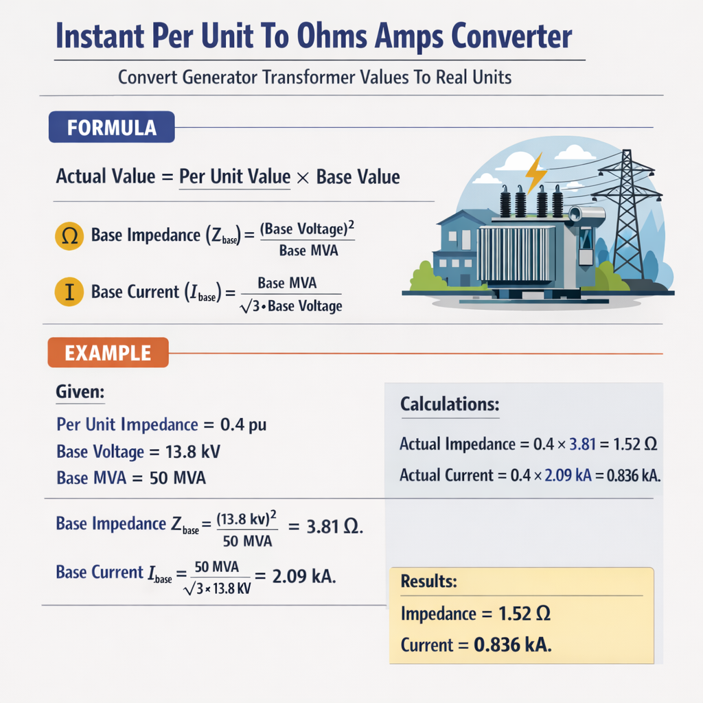
Primary base formulas (three-phase)
Z_base = (V_base2) / S_baseI_base = S_base / (sqrt(3) × V_base)
Z_actual = Z_pu × Z_base
Z_pu = Z_actual / Z_base
I_actual = I_pu × I_base
I_fault (three-phase) ≈ V_line / (sqrt(3) × Z_actual)
Variable explanations and typical engineering units
- V_base: line-to-line voltage, in volts or kilovolts (V or kV). For single-phase use line-neutral voltage.
- S_base: apparent power base, in VA or commonly MVA.
- Z_base: base impedance in ohms (Ω). If V_base in kV and S_base in MVA, Z_base = (kV2)/MVA yields Ω.
- I_base: base current in amperes (A). For three-phase networks: I_base = S_base (VA) / (√3 × V_base (V)).
- Z_actual: actual impedance in ohms (Ω) as measured or referred to a terminal.
- Z_pu: impedance in per-unit (dimensionless) on the chosen base.
- I_pu: current in per-unit (dimensionless).
Conversion relationships between different bases
When you must convert a per-unit impedance from one base set (S_base_old, V_base_old) to another (S_base_new, V_base_new) use: Z_pu_new = Z_pu_old × (S_base_new / S_base_old) × (V_base_old / V_base_new)2 Derivation outline:- Z_actual = Z_pu_old × Z_base_old.
- Z_base_old = V_base_old2 / S_base_old.
- Z_pu_new = Z_actual / Z_base_new = Z_pu_old × (Z_base_old / Z_base_new).
- Replace Z_base expressions and simplify to the formula above.
Typical base values and extensive lookup tables
| System Voltage (kV) | Z_base (Ω) for S_base = 100 MVA | I_base (A) for S_base = 100 MVA |
|---|---|---|
| 400.0 | 1600.00 | 144.34 |
| 230.0 | 529.00 | 250.66 |
| 132.0 | 174.24 | 438.35 |
| 69.0 | 47.61 | 837.17 |
| 33.0 | 10.89 | 1752.48 |
| 13.8 | 1.9044 | 4183.00 |
| 11.0 | 1.21 | 5252.27 |
| 6.6 | 0.4356 | 8760.55 |
| 0.415 | 0.001722 | 139189.57 |
| Equipment | Typical per-unit impedance ranges | Engineering note |
|---|---|---|
| Large steam turbine generator (synchronous) | X_d (synchronous): 1.0–2.5 pu | Use machine datasheet for transient/subtransient values; X" typically 0.15–0.3 pu. |
| Hydro generator | X_d: 0.8–1.8 pu | Lower transient reactances common for hydro units. |
| Power transformer (100 MVA) | Z%: 7–15% | Express as Z_pu = Z%/100 on transformer rating base. |
| Distribution transformer (<=5 MVA) | Z%: 4–8% | Lower impedance to support feeder fault currents. |
| Transmission line (short) | Z: small fractional ohms/km | Model with series impedance per km then convert to system base. |
Step-by-step procedures for common conversions
Procedure: per-unit to ohms (generator or transformer)
- Select the correct S_base and V_base for the equipment terminal where Z_pu is specified. If the device uses its own MVA rating as base, use that or convert using the base conversion formula.
- Compute Z_base = V_base2 / S_base (ensure units consistent: kV2/MVA yields Ω).
- Compute Z_actual = Z_pu × Z_base.
- Use Z_actual to compute currents or fault levels: I = V_line / (sqrt(3) × Z_actual).
Procedure: ohms to per-unit
- Determine S_base and V_base used in system model.
- Compute Z_base.
- Z_pu = Z_actual / Z_base.
Two real-case worked examples with full development
Case 1 — Synchronous generator: compute actual reactance and fault current
Problem statement:- Generator nameplate: 50 MVA, 13.8 kV (line-to-line).
- Subtransient reactance X" = 0.20 pu (given on generator base 50 MVA).
- Compute X" in ohms and three-phase bolted fault initial symmetrical current at generator terminals (fault bolted to ground on the generator terminal bus, neglect system external sources).
- S_base = 50 MVA (use generator base, since Z_pu given on machine base).
- V_base = 13.8 kV.
- Denominator = 1.732 × 0.76176 = 1.3186.
- I_fault = 13800 / 1.3186 ≈ 10470 A.
- Use transient/subtransient reactance appropriate for the time frame of the fault current (subtransient for initial peak).
- Include system external impedances and transformer leakage when connected to an infinite bus — the above assumes isolated generator fault.
Case 2 — Power transformer: percent impedance to ohms and to per-unit on alternate base
Problem statement:- Transformer rating: 100 MVA, 230/13.8 kV, nameplate Z% = 10.0% (on 100 MVA rating).
- Objective A: Compute equivalent series impedance on HV and LV terminals in ohms (referred to HV and LV respectively).
- Objective B: Convert transformer impedance to per-unit on a system base of 200 MVA and 13.8 kV low-voltage base (for network study).
- Original base: S_base_old = 100 MVA, V_base_old (LV) = 13.8 kV.
- New system base: S_base_new = 200 MVA, V_base_new (LV system) = 13.8 kV (same voltage, double power base).
- Z_actual from nameplate = 0.10 × Z_base_LV_old = 0.19044 Ω.
- New Z_base_LV (200 MVA) = (13.82) / 200 = 190.44 / 200 = 0.9522 Ω.
- Z_pu_new = Z_actual / Z_base_new = 0.19044 / 0.9522 = 0.20 pu. Validation complete.
- Transformer percent impedance on nameplate is referenced to rated MVA; conversion to system base is mandatory before network combination.
- If voltage bases differ, include squared voltage ratio in conversion formula.
Advanced conversions: single-phase, neutral grounding and asymmetrical faults
Single-phase base choices
For single-phase equipment or phase-to-ground calculations, use single-phase bases: Z_base_single = (V_base_phase2) / S_base_single where V_base_phase is the phase voltage and S_base_single is the single-phase base VA. Common practice: keep S_base three-phase and use phase voltage derived from line-to-line (V_phase = V_line / sqrt(3)) and then compute single-phase Z_base accordingly.Neutral grounding and zero-sequence conversion
Zero-sequence impedances require specific base selection because their reference is often different (ground path). When converting Z0 between bases:- Use same procedure but ensure V_base corresponds to phase voltage for zero-sequence calculations.
- Be careful when referring transformer vector groups — zero-sequence transformation depends on winding connection (delta blocks zero-sequence between windings, wye provides path).
Practical tips and best practices for accuracy
- Always record the base MVA and base voltage associated with any per-unit data on equipment nameplates or datasheets.
- Prefer using the equipment rating base for transformer and machine per-unit values, then convert to the study base consistently.
- Keep units consistent: kV and MVA pair gives Z in ohms without additional scaling; convert to volts and VA if using SI base units.
- Document if impedances are given as percent (Z%) — convert to pu by dividing by 100 and noting base.
- For protection studies include transient reactances (X', X") appropriate to time frame; steady-state fault currents use synchronous reactance for sustained conditions.
- When assembling networks with multiple voltage levels, select a single global S_base and keep V_base per voltage level consistent with bus nominal voltages.
Additional conversion examples and edge cases
Example: converting transmission line series impedance to per-unit on 100 MVA base
Given:- Line impedance per km: Z_line = 0.05 + j0.40 Ω/km.
- Line length: 100 km.
- System study base: 100 MVA, 230 kV.
- Z_total_actual = Z_line × length = (0.05 + j0.40) × 100 = 5 + j40 Ω.
- Z_base (230 kV, 100 MVA) = 529 Ω (see table).
- Z_pu = Z_total_actual / Z_base = (5 + j40) / 529 ≈ 0.00946 + j0.07564 pu.
Standards, normative references and further authoritative reading
Key standards and references:- IEEE Std 141 (Red Book) — Electrical Power Distribution for Industrial Plants: general power system conversion practices. https://standards.ieee.org/
- IEEE Std C37.010 — Application Guide for AC High-Voltage Circuit Breakers. https://standards.ieee.org/
- IEC 60076 series — Power transformers — design, testing and impedance definitions. https://www.iec.ch/
- NIST Reference on units and quantities for electrical engineering. https://www.nist.gov/
- CIGRE technical brochures on transformer impedance and short-circuit calculation methods. https://www.cigre.org/
Common pitfalls and verification checks
- Unit mismatch: mixing kV with V or MVA with kVA leads to errors of orders of magnitude; always normalize units before calculation.
- Incorrect voltage base selection: using HV base for LV impedance without appropriate conversion results in erroneous pu values.
- Neglecting transformer vector group constraints for zero-sequence paths when computing ground fault currents.
- For fault studies, ensure use of appropriate reactance type (subtransient for initial peak, transient for intermediate times, synchronous for steady-state).
- When combining impedances in pu, ensure all are on the same base — otherwise convert using the base conversion formula.
SEO optimized summary of conversion workflow (quick reference)
- Select S_base and V_base per voltage level.
- Compute Z_base = V_base2 / S_base and I_base = S_base / (√3 × V_base).
- Convert Z_pu to ohms: Z_actual = Z_pu × Z_base.
- Convert ohms to pu: Z_pu = Z_actual / Z_base.
- Convert between pu bases: Z_pu_new = Z_pu_old × (S_new / S_old) × (V_old / V_new)2.
- Use per-unit currents: I_actual = I_pu × I_base or directly compute I_actual = V_line / (√3 × Z_actual).
References for practical implementation and software tools
- PSS®E user manuals and conversion examples for system base handling. https://new.siemens.com/global/en/products/energy.html
- ETAP technical notes on per-unit conversions and protective relay settings. https://etap.com/
- Open-source libraries and academic references demonstrating per-unit standardization and conversion routines for power system simulation (e.g., MATPOWER documentation). http://www.pserc.cornell.edu/matpower/