Rapid single-phase service sizing improves safety, efficiency, and compliance for mixed residential and commercial loads.
This calculator methodology yields accurate 120/240V demand results for diversified circuits and motor loads schedules.
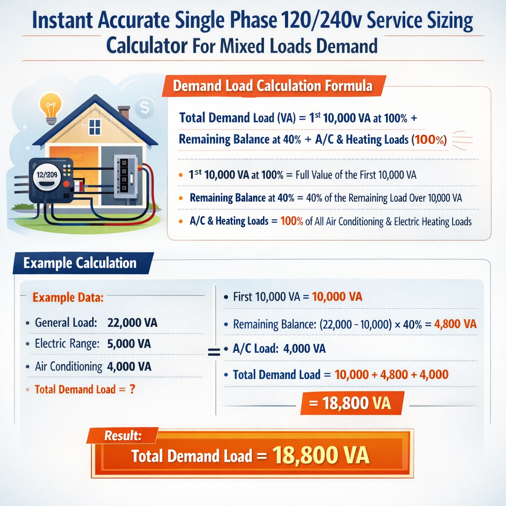
Single-Phase 120/240 V Service Sizing Calculator for Mixed Load Demand (Minimum Service Current)
Overview of Instant Accurate Single Phase 120/240V Service Sizing Calculator For Mixed Loads Demand
This article documents a technically rigorous method for calculating required service ampacity for single‑phase 120/240 V split‑phase systems serving mixed load sets. The algorithm accounts for continuous and non‑continuous loads, diversified demand factors, motor starting contributions, and typical code-based adjustments to produce an instant accurate sizing recommendation. The content is applicable to engineers, electrical contractors, and design professionals seeking a deterministic, code‑aware approach. It synthesizes NEC/IEC guidance, practical diversity assumptions, and formulaic steps suitable for embedding into a calculator or executing manually for design validation.Scope, assumptions, and key definitions
- Scope: Single‑phase 120/240 V center‑tapped neutral services up to 400 A typical residential/commercial services.
- Assumptions: Balanced split‑phase where applicable, power factor (PF) default = 1.0 for resistive loads, PF noted for motors when required.
- Definitions:
- Connected load: Sum of individual nameplate wattages or amperages before diversity.
- Demand load: Applied load after demand factors and diversity adjustments.
- Continuous load: Load expected to run for 3 hours or more (NEC definition).
Standards and normative references
- NEC (NFPA 70) — Article 220: Branch‑circuit, feeder, and service calculations. https://www.nfpa.org/
- IEC 60364 — Electrical installations of buildings (general principles and load calculations). https://www.iso.org/ and https://www.iec.ch/
- IEEE Std 142 — Grounding of Industrial and Commercial Power Systems. https://standards.ieee.org/
- NEMA MG1 — Motors and generators performance data. https://www.nema.org/
- Manufacturer data sheets for specific equipment (motors, HVAC, inverters) — primary source for nameplate FLA and starting torque/locked rotor currents.
Fundamental electrical formulas and variable explanations
These formulas are expressed in plain HTML and used throughout sizing and example sections.
Explanation:
- P = Active power in watts (W).
- V = Line‑to‑line voltage in volts. For split‑phase 120/240 V service, use 120 V for single‑pole loads, 240 V for two‑pole loads.
- I = Current in amperes (A).
Explanation:
- PF = Power factor (dimensionless). PF = 1.0 for pure resistive loads; motors typically 0.8–0.9 at rated load.
- Use PF < 1 when motor or reactive loads predominate for more accurate current estimates.
Explanation:
- S = Apparent power (VA) used for transformer and service capacity considerations.
Explanation:
- Compute demand power after applying demand factors; divide by 240 V for two‑pole loads or compute each leg for 120 V loads as applicable.
5) Continuous load adjustment per NEC: Service ampacity must be not less than 125% of continuous load.
Explanation:
- Continuous load (expected 3 hours or more) must be multiplied by 125% when sizing conductors and OCPDs.
Common load catalog: typical nameplate values and single‑phase currents
| Equipment | Typical Power (W) | Voltage | Current (A) | Continuous? | Notes |
|---|---|---|---|---|---|
| Lighting (LED whole house) | 1200 | 120 | 10 | No | General lighting circuit, PF ≈ 0.9 |
| Receptacles (general) | 1500 | 120 | 12.5 | No | Loads vary; diversity applies |
| Electric Range (typical) | 8000 | 240 | 33.33 | No | May be treated with demand factors |
| Electric Dryer | 5400 | 240 | 22.5 | No | Often a single 30 A circuit |
| Central AC (3 ton) | ≈ 3500 (running) | 240 | 14.6 | Yes (cyclic) | Starting currents much higher (LRA) |
| Water heater (4500 W) | 4500 | 240 | 18.75 | Yes | Continuous – apply 125% |
| Electric vehicle charger (Level 2) | 7000 | 240 | 29.17 | Yes | Often continuous; apply 125% |
| 3 HP motor (nameplate) | ≈ 2238 | 240 | ≈9.33 | No | FLA per NEMA varies; starting amps higher |
| Single‑phase welder (small) | 6000 | 240 | 25 | No | Intermittent duty; use duty cycle |
| Subpanel (misc small circuits) | 2000 | 120/240 | ≈8.3 | No | Sum of small loads |
Demand factor guidance and typical tables
Demand factors reduce connected load to realistic expected simultaneous draw. Use code tables where applicable (NEC 220) and manufacturer recommendations for equipment. The table below gives example demand factors used by many calculators; adapt to local code requirements.
| Load Group | Connected Load Range | Representative Demand Factor | Application Notes |
|---|---|---|---|
| General lighting & receptacles | 0–3 kW | 100% | Small loads fully applied |
| General lighting & receptacles | 3–10 kW | 75–100% | Use NEC Table 220.12 for guidance |
| Household appliances (ranges, dryers) | Ranges: per appliance | NEC reduced demand factors apply | NEC 220.55 and 220.56 guidance for ranges and dryers |
| Water heaters | Single or multiple | 100% (continuous) | Apply continuous load rules (125%) |
| Electric vehicle chargers | Per charger | Apply 100% if continuous; consider load management | EV chargers often considered continuous by operation profile |
| Motors (aggregate) | Sum FLA | NEC 430.24 and Table-based adjustments | Apply larger motor contributions and demand factors per motor type |
| Small commercial mixed | Depends on usage | 50–100% | Engineer assessment required; use load scheduling |
Calculator algorithm: step‑by‑step methodology
- Inventory all connected loads: list nameplate watts or amps, voltage, continuous flag, motor horsepower, and special starting characteristics.
- Convert nameplate amps to watts where needed: P = V × I (include PF when relevant).
- Group loads by type: 120 V single‑pole, 240 V two‑pole, motors, heating (continuous), and others.
- Apply demand factors:
- Lighting and receptacles: NEC tables or standard diversity percentages.
- Appliances/ranges/dryers: NEC-specific demand table application.
- Motors: apply NEC guidance for feeder sizing and concurrent starting expectations.
- Sum demanded watts for 120 V and 240 V groups. Convert group wattage to amps: I = P / V.
- Identify continuous loads and apply 125% multiplier for conductor and OCPD sizing.
- Calculate required service ampacity = max(aggregate demanded amps, continuous adjusted amps) and round to next standard service size (100 A, 150 A, 200 A, 225 A, 400 A, etc.).
- Verify conductor ampacity, voltage drop (recommend ≤3% for feeders), and short-circuit/coordination requirements.
Algorithmic details for motors and starting currents
Motors introduce non‑steady state phenomena (inrush/locked rotor). For service sizing:
- Use motor nameplate FLA for steady‑state demand.
- For short duration diversity calculations, consider a fractional allowance for starting surge aggregated across motors that might start simultaneously.
- For large motors where starting significantly increases protective device rating, coordinate with NEC 430 for overload protection and sizing of conductors.
Voltage drop and conductor sizing considerations
After service ampacity is determined, choose conductor size to satisfy both ampacity and voltage drop limits. Use the formula below for single‑phase circuits.
Explanation:
- Vd = Voltage drop in volts.
- L = One‑way conductor length (ft).
- I = Current in amperes.
- R = Conductor resistance in ohms per 1000 ft (depends on material and size).
Example 1 — Residential single‑family dwelling service sizing (detailed)
Problem statement: Size a 120/240 V single‑phase service for a home with the following connected loads:
- Lighting & general receptacles: 3.0 kW (120 V loads)
- Electric range: 8.0 kW (240 V)
- Electric dryer: 5.4 kW (240 V)
- Electric water heater: 4.5 kW (240 V), continuous
- Central AC (3 ton): 3.5 kW running at 240 V (motor), starting LRA ignored for steady demand
- Electric vehicle charger: 7.0 kW (240 V), likely continuous
Step 1 — Convert and group loads into 120 V and 240 V groups.
- 120 V lighting & receptacles: P1 = 3,000 W
- 240 V fixed appliances and equipment: Range P2 = 8,000 W; Dryer P3 = 5,400 W; Water heater P4 = 4,500 W (continuous); AC P5 = 3,500 W; EV charger P6 = 7,000 W (continuous)
Step 2 — Apply demand factors where code permits. For this example use conservative simplified demand assumptions:
- Lighting & receptacles (3.0 kW): apply 100% = 3,000 W (small house assumption)
- Range: per NEC Table for a single range, for simplicity we assume 8.0 kW demand at 100% = 8,000 W (code tables can reduce this)
- Dryer: assume 5.4 kW at 100% = 5,400 W
- Water heater: continuous 4.5 kW → apply 125% for conductor sizing but included now as 4,500 W for demand summation
- AC: 3,500 W (running) — treat as non‑continuous for service diversity but include full running load
- EV charger: 7,000 W, continuous → included in demand and later multiplied by 125% for conductor/OCPD sizing
Step 3 — Sum 240 V loads (240 V two‑pole):
Convert to equivalent service amps at 240 V: I240 = P240 / 240 = 28,400 / 240 = 118.33 A
Step 4 — Add 120 V loads (presented as watts but distributed across both legs; for conservative calculation include full 120 V load converted to equivalent two‑pole wattage):
Convert 120 V lighting 3,000 W to equivalent at 240 V perspective: P120_equiv = 3,000 W (still 3,000 W contributing to total demand). Aggregate P_total = 28,400 + 3,000 = 31,400 W
Step 5 — Continuous load adjustments: Water heater (4,500 W) and EV charger (7,000 W) are continuous: continuous_sum = 4,500 + 7,000 = 11,500 W
Step 6 — Round to nearest standard service size and verify margins. Common standard sizes: 100 A, 150 A, 200 A. Choose 150 A service.
Step 7 — Check voltage drop and conductor ampacity:
- 150 A at 240 V gives apparent power 36 kVA, close to computed 34.275 kW demand.
- Conductors sized for 150 A (typical copper: 1/0 AWG THHN at 75°C ampacity ~150 A; check insulation and installation conditions).
Final recommendation: Provide a 150 A, 120/240 V single‑phase service with conductors and OCPDs sized to handle 125% of continuous loads, verify motor starting effects on main lug temperatures, and confirm compliance with local NEC amendments and inspection.
Example 2 — Small commercial workshop with mixed motors and resistive loads (detailed)
Problem statement: Design a 120/240 V single‑phase service for a small woodworking shop with the following connected loads:
- Lighting and receptacles: 4.0 kW (120 V)
- Dust collector motor: 5 HP, single‑phase, 240 V
- Planer motor: 3 HP, single‑phase, 240 V
- Air compressor: 2 HP, 240 V (intermittent)
- Small kiln: 6.0 kW, 240 V (continuous while firing)
- Miscellaneous welders and pumps: combined 4.0 kW intermittently
Step 1 — Nameplate and typical FLA conversions (use NEMA typical FLA approximations; verify with actual nameplates):
- 5 HP single‑phase motor ≈ 23 A FLA at 240 V (typical; check manufacturer)
- 3 HP motor ≈ 14 A FLA at 240 V
- 2 HP motor ≈ 9.3 A FLA at 240 V
Step 2 — Convert motor FLA to watts for aggregation (use P = V × I × PF; assume PF = 0.9 for motors):
- Dust collector: P_dc = 240 × 23 × 0.9 = 4,968 W ≈ 4.97 kW
- Planer: P_pl = 240 × 14 × 0.9 = 3,024 W ≈ 3.02 kW
- Compressor: P_cmp = 240 × 9.3 × 0.9 = 2,005 W ≈ 2.01 kW
Step 3 — Sum resistive and continuous loads:
- Lighting & receptacles P1 = 4,000 W
- Kiln (continuous) P2 = 6,000 W (apply 125% later)
- Misc intermittent welders/pumps P3 = 4,000 W
Step 4 — Aggregate running loads (motors running assumed not simultaneous all at full load; but for conservative planning include full running FLA):
Total connected P_total = P1 + P2 + P3 + P_motors = 4,000 + 6,000 + 4,000 + 10,000 = 24,000 W
Step 5 — Continuous load adjustment: Kiln 6,000 W continuous → continuous_sum = 6,000 W → adjusted continuous = 6,000 × 1.25 = 7,500 W
Step 6 — Motor starting contribution: Consider locked rotor and potential simultaneous starting. Use simplified diversity: only one large motor (dust collector) likely to start at a time; apply a starting allowance of 200% for largest motor for a short interval or use load management. For steady‑state service sizing, include only running currents but verify bus stability during starting events.
If planning for worst‑case steady starting draw (temporary peak) consider max transient current:
- Largest motor locked rotor may be 500% of FLA. For dust collector: starting current ≈ 23 A × 5 = 115 A additional for short time.
- But starting currents are transient and do not increase steady service ampacity. Ensure main protective device and feeder conductor temperature limits account for cumulative heating duty.
Step 7 — Round to standard service size. Computed requirement ≈ 106.25 A → choose 150 A service to provide margin and allow future expansion.
Step 8 — Verify conductor ampacity, select appropriate overcurrent protection, and consider soft‑start or reduced voltage starters to mitigate service voltage sag and starting currents. Check NEC 430 for motor protection and conductor sizing rules.
Final recommendation: Provide 150 A 120/240 V single‑phase service with measured starting controls or soft‑starters for large motors, and wiring sized to handle 125% of continuous loads. Consider load sequencing (interlocks) or demand management for simultaneous motor starts and kiln operation.
Implementation notes for an instant calculator
Key implementation components for a production calculator:
- Input schema: itemized loads with fields — nameplate watts or amps, voltage, continuous flag, motor HP, PF, largest motor flag, and starting factor.
- Unit conversions: automated conversion between amps and watts given PF and voltage.
- Demand factor database: include configurable tables for local code variations (NEC, IEC, country specific rules).
- Continuous load handling: automatic 125% multiplier and separate conductor/OCPD output.
- Motor handling: include steady FLA, optionally compute locked rotor and inrush allowances and present transient/steady recommendations.
- Rounding logic: map continuous computed ampacities to standard service sizes and suggest conductor sizes and voltage drop checks.
- Reporting: provide a detailed step log (inputs → conversions → applied demand factors → final sizing) suitable for permitting and documentation.
User interface and UX tips for rapid, accurate results
- Provide prefilled lists of common loads with typical wattages to accelerate input.
- Allow users to override PF, demand factors, and motor starting percentages for special equipment.
- Display warnings for continuous load violations, excessive voltage drop, and potential NEC noncompliance.
- Include links to normative references presented below for transparency.
Verification, safety, and compliance checks
- Confirm conductor ampacity with NEC 310 or local equivalent; consider ambient temperature, bundling, and insulation rating.
- Size overcurrent devices to protect the conductor but not exceed equipment limitations (NEC 240 and 430 rules).
- Grounding electrode system and equipment grounding conductor sizing per NEC 250 and local practices.
- Verify short‑circuit and coordination using fault current calculations; coordinate main breakers with branch devices for selective coordination where required.
- Perform voltage drop checks for long feeders; recommended maximum 3% for feeders and branch circuits combined to maintain equipment efficiency.
References and authoritative external links
- National Fire Protection Association (NFPA) — NFPA 70®: National Electrical Code® (NEC): https://www.nfpa.org/NEC
- International Electrotechnical Commission (IEC) — IEC 60364 series: https://www.iec.ch/
- U.S. Department of Energy: Energy Saver and equipment typical load information: https://www.energy.gov/
- NEMA (National Electrical Manufacturers Association): Motor and equipment data: https://www.nema.org/
- IEEE Standards: grounding and power system guides: https://standards.ieee.org/
- Manufacturer data sheets and nameplate verification — always consult OEM documentation for motor FLA, locked rotor current, and duty cycle characteristics.
Practical checklist before finalizing service installation
- Verify nameplate data on all motors and appliances; update calculator inputs accordingly.
- Apply applicable local code demand tables; do not substitute simplified diversity where code requires table application.
- Account for continuous loads with 125% conductor/OCPD sizing.
- Assess motor starting and consider soft starters, VFDs, or load sequencing to reduce utility impact.
- Check voltage drop for worst‑case feeder length and adjust conductor size if necessary.
- Document calculation and provide permit‑grade load summary showing assumptions and references.
Key takeaways for accurate single‑phase 120/240 V service sizing
- Aggregate connected load, convert units consistently, and group by voltage and type (continuous, motor, resistive).
- Apply code‑based demand factors and 125% continuous adjustments; motors require special attention for starting currents.
- Select a service rating that covers both steady‑state demand and realistic transient behavior, then validate conductors, OCPDs, and voltage drop.
- Automate the workflow in a calculator with an auditable step log, normative references, and configurable local code tables for rapid, accurate results.
Further reading
- NEC Article 220 — Branch‑Circuit, Feeder, and Service Calculations: https://www.nfpa.org/
- NEC Article 430 — Motors, Motor Circuits, and Controllers: https://www.nfpa.org/
- IEC 60364 — Design and verification of electrical installations: https://www.iec.ch/
- IEEE Std 141 — Reference Book: Electric Power Distribution for Industrial Plants: https://standards.ieee.org/
If you need, I can produce a spreadsheet-ready worksheet or a web API specification for implementing this calculator logic, including configurable demand factor tables and motor inrush models for precise transient analysis.