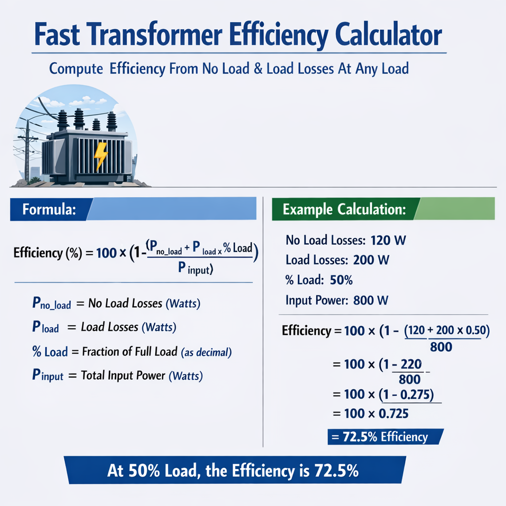
This article provides a fast transformer efficiency calculator method for engineering and asset management operations.
Compute efficiency from no-load and load losses at any load using standardized electrical formulas precisely.
You exceeded your current quota, please check your plan and billing details. For more information on this error, read the docs: https://platform.openai.com/docs/guides/error-codes/api-errors.
Background and core concepts
Transformers dissipate energy through two primary mechanisms: core (no-load) losses and winding (load) losses. Core losses (also called iron or no-load losses) occur due to magnetization and hysteresis in the core and are effectively constant for a given applied voltage and frequency. Winding losses (copper or load losses) are I^2R dependent and scale with the square of load current; they are specified at rated current and vary with actual load. Understanding efficiency at any load requires combining these losses with delivered output power. Accurate practical calculation needs rated data: rated apparent power S_rated, rated current I_rated, no-load loss P_no-load, and load loss at rated current P_load_rated. The standard approach models total losses as:P_total = P_no-load + P_load_rated · (k)2
where k is the per-unit load (k = S_load / S_rated). Output active power depends on load and power factor:P_out = S_rated · k · pf
Mathematical model and formula set
This section lists the primary formulas, using plain HTML elements for exponents and subscripts.Primary formulas
- k = S_load / S_rated — per-unit loading factor (dimensionless).
- P_total = P_no-load + P_load_rated · k2 — total losses at load k.
- P_out = S_rated · k · pf — active power delivered to load (W) for single- or three-phase apparent S in VA.
- η(k) = P_out / (P_out + P_total) — efficiency at per-unit load k (decimal, multiply by 100 for percent).
- k_opt = sqrt(P_no-load / P_load_rated) — per-unit load at which efficiency is maximum (derived by equating P_no-load = P_load_rated · k2).
Variable definitions and typical engineering units
- S_rated: Rated apparent power (VA, typically kVA or MVA).
- S_load: Apparent power supplied at actual conditions (VA).
- k: Per-unit load (dimensionless).
- I_rated: Rated current (A). For three-phase: I_rated = S_rated / (√3 · V_secondary).
- P_no-load: No-load (core) losses (W), measured at rated voltage and frequency.
- P_load_rated: Load (copper) losses (W) at rated current, typically measured and supplied by manufacturer.
- pf: Power factor (lagging typically 0.8–1.0, dimensionless).
- P_total: Sum of core and load losses at operating condition (W).
- P_out: Active output power delivered to load (W).
- η: Efficiency (decimal or %).
Detailed loss behavior and practical corrections
Core losses are functionally dependent on applied voltage and frequency. For small voltage deviations, P_no-load scales approximately with V2, but hysteresis contributes non-linear components. For practical calculator design, when supply voltage deviates significantly from rated voltage, use measured or corrected values:- P_no-load(V) ≈ P_no-load,rated · (V / V_rated)2 (approximate).
- For frequency deviations, magnetic characteristics require manufacturer curves or laboratory data.
R(T) = R_20 · [1 + α · (T - 20 °C)]
where α is copper temperature coefficient ≈ 0.00393/°C. For high accuracy include this when loading results in significant heating.Tables of typical transformer ratings and loss values
Below are tables of common distribution and power transformer ratings and typical published losses. Use these as baseline inputs for the efficiency calculator. All values are typical orders of magnitude; always confirm with manufacturer data.| Rating (kVA) | Primary Voltage (kV) | Secondary Voltage (V) | P_no-load (W) | P_load_rated (W) | I_rated (A) (sec) | Typical pf |
|---|---|---|---|---|---|---|
| 25 | 11 | 415 | 30 | 220 | 35 | 0.8–1.0 |
| 100 | 11 | 415 | 70 | 600 | 139 | 0.8–1.0 |
| 250 | 11 | 415 | 150 | 1500 | 347 | 0.8–1.0 |
| 500 | 33 | 415 | 300 | 3600 | 693 | 0.8–1.0 |
| 1000 | 33 | 415 | 600 | 9000 | 1386 | 0.8–1.0 |
| 2500 | 110 | 690 | 1500 | 21000 | 2177 | 0.8–1.0 |
| 10000 | 132 | 11,000 | 6000 | 90000 | 5250 | 0.8–1.0 |
| Load (%) | k (per-unit) | Factor for P_load (k2) | Explanation |
|---|---|---|---|
| 10 | 0.10 | 0.0100 | Very light loading, losses dominated by core losses |
| 25 | 0.25 | 0.0625 | Low load, P_cu small compared to P_core |
| 50 | 0.50 | 0.2500 | Moderate load; both losses matter |
| 75 | 0.75 | 0.5625 | High utilization; load losses significant |
| 100 | 1.00 | 1.0000 | Rated load, reference for P_load_rated |
| 125 | 1.25 | 1.5625 | Overload; watch thermal limits and temperature correction |
Step-by-step calculator algorithm
To implement a fast calculator (spreadsheet or software), follow this deterministic algorithm. This also clarifies units and rounding rules for engineering reporting.- Input rated parameters: S_rated, P_no-load, P_load_rated, and rated voltages.
- Enter operating load either as percent or apparent S_load. Convert to per-unit: k = S_load / S_rated.
- Select or input power factor pf (default 1.0 or 0.8 lagging typical).
- Compute load loss at k: P_cu = P_load_rated · k2.
- Compute total losses: P_total = P_no-load + P_cu.
- Compute output power: P_out = S_rated · k · pf (W).
- Compute efficiency: η = P_out / (P_out + P_total) (return as % with desired precision).
- Optional: compute k_opt = sqrt(P_no-load / P_load_rated) and efficiency at k_opt to check where maximum occurs.
Accuracy considerations
- Use manufacturer-certified losses for best accuracy. Standard test methods are specified in IEC and IEEE standards.
- Correct load losses for ambient and hotspot temperatures when assessing thermal capability.
- Account for voltage variations when supply is not exactly rated; adjust P_no-load accordingly if necessary.
Worked example 1 — 1000 kVA medium-power distribution transformer (step-by-step)
Problem statement: A three-phase 1000 kVA transformer has documented losses: P_no-load = 600 W and P_load_rated = 9000 W. Determine efficiency at 75% load with pf = 0.85 lagging. Also compute per-unit optimum load (k_opt) and maximum efficiency at that load. Step 1: Convert load to per-unit:k = 0.75 (75% load)
Step 2: Compute load loss at 75%:P_cu = P_load_rated · k2 = 9000 · 0.752 = 9000 · 0.5625 = 5062.5 W
Step 3: Compute total losses:P_total = P_no-load + P_cu = 600 + 5062.5 = 5662.5 W
Step 4: Compute output active power: Rated apparent S_rated = 1000 kVA = 1,000,000 VAP_out = S_rated · k · pf = 1,000,000 · 0.75 · 0.85 = 637,500 W
Step 5: Compute efficiency:η = P_out / (P_out + P_total) = 637,500 / (637,500 + 5,662.5) = 637,500 / 643,162.5 ≈ 0.9912
Expressed as percentage:η ≈ 99.12%
Step 6: Compute k_opt:k_opt = sqrt(P_no-load / P_load_rated) = sqrt(600 / 9000) = sqrt(0.0666667) ≈ 0.2582
This indicates the theoretical maximum efficiency occurs at ~25.8% loading because core losses are relatively small here; verify maximum efficiency: Compute P_cu at k_opt:P_cu_opt = 9000 · 0.25822 ≈ 9000 · 0.06667 ≈ 600 W
Total losses at k_opt:P_total_opt = 600 + 600 = 1,200 W
Output power at k_opt (pf = 0.85):P_out_opt = 1,000,000 · 0.2582 · 0.85 ≈ 219,470 W
Efficiency at k_opt:η_opt = 219,470 / (219,470 + 1,200) ≈ 219,470 / 220,670 ≈ 0.9946
So η_opt ≈ 99.46%. Interpretation: - At 75% load, the transformer is highly efficient (~99.12%). - Maximum efficiency occurs at a lower per-unit load (~25.8%) because of parameter magnitudes; practical systems prioritize other considerations (e.g., peak loading, losses over annual energy).Worked example 2 — 250 kVA distribution transformer with non-unity pf and voltage variation
Problem statement: A 250 kVA pad-mounted transformer: P_no-load = 150 W, P_load_rated = 1500 W at rated voltage. Evaluate efficiency at 40% load, pf = 0.9. Additionally consider supply voltage is 2% above rated. Apply approximate correction for core loss and recompute efficiency. Step 1: Per-unit load:k = 0.40
Step 2: Nominal P_cu at 40%:P_cu = 1500 · 0.402 = 1500 · 0.16 = 240 W
Step 3: Correct P_no-load for +2% voltage: Approximate scaling P_no-load(V) ≈ P_no-load,rated · (V/V_rated)2P_no-load_corrected = 150 · (1.02)2 = 150 · 1.0404 = 156.06 W
Step 4: Compute total losses:P_total = 156.06 + 240 = 396.06 W
Step 5: Compute output power:P_out = 250,000 · 0.40 · 0.9 = 90,000 W
Step 6: Efficiency:η = 90,000 / (90,000 + 396.06) ≈ 90,000 / 90,396.06 ≈ 0.9956
η ≈ 99.56%
Notes: - Voltage increase slightly raises core losses and marginally reduces efficiency. - For accuracy, manufacturers publish no-load loss vs. voltage curves; use those for more than +/- 5% deviation.Using the calculator for energy cost and annual loss estimation
A useful extension of the fast efficiency calculator computes annual energy loss and cost based on load profile. Outline:- Specify hourly or time-blocked load fractions k(t) and pf(t).
- For each time step compute P_total(t) as above.
- Energy loss in interval Δt: E_loss = P_total(t) · Δt (kWh = W · hours / 1000).
- Sum energy losses across intervals for annual loss estimate.
- Multiply by electricity price (currency/kWh) to get annual cost.
E_loss_step (kWh) = [P_no-load + P_load_rated · k(t)2] · Δt_h / 1000
This approach enables life-cycle cost comparisons for transformer selection and optimization.Design and standards references
For regulatory and test method guidance, consult the following authoritative references:- IEC 60076 series — Power transformers (general requirements, losses, temperature rise, short-circuit tests). https://www.iec.ch
- IEEE C57.12 — IEEE Standard for Transformers: performance and test methods. https://standards.ieee.org
- NEMA TR 1 — Transformers Rationalized Metric and Electrical Data. https://www.nema.org
- IEC 60076-1 — Loading guide for transformers (useful for temperature corrections).
Implementation notes for an automated calculator
Consider these engineering and software best practices:- Input validation: require units and detect unit mismatches (kVA vs VA).
- Allow user to provide losses at a reference voltage different from rated and include scaling options.
- Support three-phase conversion for rated current: I_rated = S_rated / (√3 · V_secondary).
- Provide outputs in both decimal and percentage form, and round to user-specified significant digits.
- Expose temperature correction for P_load_rated if user supplies winding temperature or ambient and load duration.
- Offer batch mode to compute efficiency curves across load percentages (0–125%) and supply CSV export for reports.
Performance visualization and tables
Presenting efficiency curves and tabulated results for standard load points increases transparency and usability. Example table template (calculator output) for a given transformer:| Load (%) | k | P_cu (W) | P_total (W) | P_out (W) | Efficiency (%) |
|---|---|---|---|---|---|
| 10 | 0.10 | 0.01 · P_load_rated | P_no-load + 0.01 · P_load_rated | S_rated · 0.10 · pf | Compute via η formula |
| 25 | 0.25 | 0.0625 · P_load_rated | P_no-load + 0.0625 · P_load_rated | S_rated · 0.25 · pf | Compute via η formula |
| 50 | 0.50 | 0.25 · P_load_rated | P_no-load + 0.25 · P_load_rated | S_rated · 0.50 · pf | Compute via η formula |
| 75 | 0.75 | 0.5625 · P_load_rated | P_no-load + 0.5625 · P_load_rated | S_rated · 0.75 · pf | Compute via η formula |
| 100 | 1.00 | 1.00 · P_load_rated | P_no-load + P_load_rated | S_rated · 1.00 · pf | Compute via η formula |
Key takeaways for engineers and asset managers
- Transformer efficiency at any load is straightforward to compute from P_no-load and P_load_rated using k2 scaling.
- Core losses are nearly constant (but voltage-dependent); copper losses scale with the square of load current.
- Maximum efficiency occurs where core losses equal load losses: k_opt = sqrt(P_no-load / P_load_rated).
- For lifecycle energy cost calculations, integrate losses across expected load profiles and apply electricity tariffs for accurate TCO comparisons.
- Always use standardized test reports (IEC/IEEE) and consider temperature and voltage corrections for precision.
- IEC 60076 Power Transformers — comprehensive international standard. https://www.iec.ch/standards
- IEEE Transformer Standards and Recommended Practices. https://standards.ieee.org/standard/C57_12_00.html
- NEMA and manufacturer datasheets for typical loss tables and temperature correction guidance. https://www.nema.org
- Technical papers on transformer energy efficiency and asset optimization (e.g., CIGRE technical brochures).