This article describes calculating minimum bending radius for cables aligned with NEC and industry standards.
Provides formulas, tables, worked examples, and guidance to implement a robust NEC-compliant calculator tool today.
Minimum Bending Radius Calculator — NEC Tool
Regulatory and normative basis for minimum bending radius
Minimum bending radius for electrical and optical cables is governed by a combination of statutory code, industry standards, and manufacturer instructions. The National Electrical Code (NFPA 70 / NEC) requires installations to avoid conductor damage and to follow manufacturer instructions; where a code-required minimum is not explicitly numeric, the authority having jurisdiction (AHJ) and manufacturer guidance define the enforceable limit.
Relevant industry standards and documents include ICEA, IEEE, IEC, TIA and Telcordia/GR series for fiber, plus UL and manufacturer datasheets; these documents provide explicit bend limits or procedures for establishing them. Always document the source for any value used in a compliance calculation and prefer manufacturer-specified radii where provided.
Fundamental formula and parameters
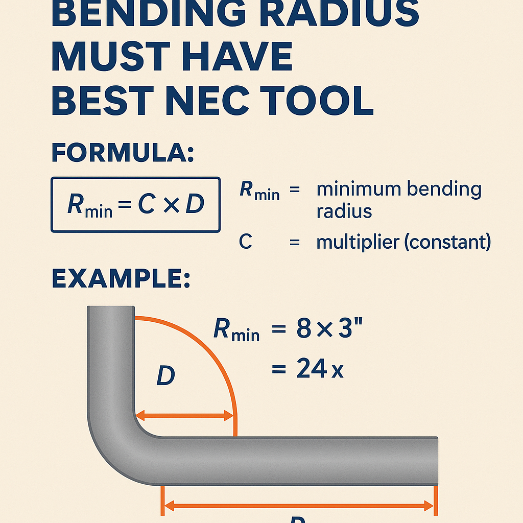
The generic engineering formula used by calculators and engineers is compact and robust:
Where:
- R_min = minimum bending radius (same units as D)
- k = bend multiplier (dimensionless) depending on cable type, construction, and application
- D = overall cable diameter (outer jacket / armor diameter)
Typical units: millimetres (mm) or inches (in). Use a consistent unit system across inputs and outputs. Conversion: 1 in = 25.4 mm.
Alternative expression for conductor-only bends
For single insulated conductors where diameter of conductor alone is relevant, the same multiplier approach applies:
- k_c is typically smaller for solid single-conductor service wires (e.g., 4–6)
- d_cond is conductor plus insulation diameter
Typical multipliers (k) for common cable classes
| Cable class | Construction / notes | Typical k multiplier | Example R_min for D = 10 mm | Example R_min for D = 25 mm |
|---|---|---|---|---|
| Single insulated conductor (solid) | Building wire, low-voltage | 4 × D | 40 mm | 100 mm |
| Single conductor (stranded, THHN/THWN) | Flexible conductors in conduit | 6 × D | 60 mm | 150 mm |
| Nonmetallic-sheathed cable (NM-B) | Residential branch wiring | 5 × D | 50 mm | 125 mm |
| Metal-clad (MC) cable | Armored cable with interlocked armor | 6–8 × D | 60–80 mm | 150–200 mm |
| Tray cable (TC) | Power and control cables for trays | 6–8 × D | 60–80 mm | 150–200 mm |
| Flexible cord | Portable equipment flex cord | 8–10 × D | 80–100 mm | 200–250 mm |
| Instrumentation / control multi-core | Shielded control cables | 8 × D | 80 mm | 200 mm |
| Low-voltage power cable (XLPE, PVC) | Building power feeders | 8–12 × D | 80–120 mm | 200–300 mm |
| Medium-voltage power cable (paper, XLPE) | 3.3 kV to 35 kV range | 10–20 × D | 100–200 mm | 250–500 mm |
| Fiber optic, tight-buffered patch cords | Indoor dynamic use | 10 × D (dynamic); 20 × D (static recommended) | 100 mm / 200 mm | 250 mm / 500 mm |
| Fiber optic, loose tube OSP cable | Outdoor, long-term installation | 15–20 × D | 150–200 mm | 375–500 mm |
| High-voltage terminations and joints | Special handling, larger radius | ≥20 × D or manufacturer-specified | ≥200 mm | ≥500 mm |
Notes about the table above:
- Values are typical industry guidance ranges; always confirm with the cable manufacturer’s datasheet.
- “Dynamic” denotes repeated flexing; “static” denotes long-term installed condition.
- NEC does not always provide a numeric multiplier for every cable type but mandates prevention of conductor damage and adherence to manufacturer instructions.
Key variables affecting bending radius and calculator inputs
Effective calculator inputs and internal checks should include:
- Cable type and standard classification (e.g., THHN, NM-B, MC, XLPE, fiber)
- Overall cable diameter D (optional: conductor diameter and jacket thickness)
- Installation mode: static (installed) or dynamic (flex, moving parts)
- Operating temperature and minimum temperature during installation (affects flexibilty)
- Bending location: free-air, tray, conduit, termination region
- Manufacturer-provided minimum bending radius override (preferred)
- Safety factor or design factor (1.0–1.25 typical for code compliance checks)
- Unit system selection (mm or inches)
Additional parameters for tight installations
- Conduit fill and friction during pull (affects allowable pulling radius)
- Number of consecutive bends and allowable tension
- For fiber: minimum bend diameter under packaging and storage conditions
Formulas and working expressions
Core formula (already shown):
Conversion formula between mm and inches:
When a safety factor (SF) is applied:
- SF typical values: 1.0 (strict compliance), 1.1–1.25 (design margin for installation tolerances)
When a manufacturer provides absolute numeric radius R_manufact, use:
Example of combining factors (units consistent):
Essential features for a best NEC-compliant bending-radius calculator
A professional, internationally usable calculator tool should implement the following features and UI/UX logic:
- Input validation: require D > 0, select cable class from a controlled vocabulary, allow manufacturer override.
- Unit handling: toggle mm/in with automatic conversion and display precision (e.g., two decimals).
- Library of default k multipliers per cable class and local code presets (NEC, IEC, etc.).
- Selection of installation type (static/dynamic) and adjustment of k accordingly.
- Safety-factor selection and automatic application to the result.
- Clear reporting: computed R_design, applied k, D, SF, and reference sources (standard or datasheet URL).
- Exportable compliance certificate: timestamped PDF/CSV reporting values, inputs, and referenced standards.
- Edge-case checks: warn if radius < manufacturer minimum, if bend occurs within terminations, or if conduit diameter precludes required radius.
- Localized normative mapping: link to NFPA/NEC, IEC, or country-specific regulations and AHJ guidance.
Algorithmic flow
- Obtain cable class and D from user or database.
- If manufacturer minimum exists, set R_manufacturer = provided value; else R_manufacturer = 0.
- Lookup default k for cable class and installation type.
- Compute R_min = k × D.
- Compute R_required = max(R_min, R_manufacturer) × SF.
- Validate R_required against installation constraints (conduit bend radius, trough geometry).
- Generate report with references and recommended corrective actions if R_required not feasible.
Detailed worked examples
Example 1 — Multi-conductor building power feeder (XLPE insulated, PVC jacket)
Scenario: Install a 3-core, 500 kcmil equivalent XLPE-insulated power feeder in conduit. Manufacturer datasheet reports an overall cable diameter D = 28.0 mm. Installation is static (installed — not flexing). The design team uses a safety factor SF = 1.1. Default k for low-voltage power cables (XLPE) is taken as 10 × D (conservative for static installs).
Step-by-step calculation:
- Given: D = 28.0 mm
- k (chosen) = 10
- Manufacturer minimum R_manufacturer = 200 mm (manufacturer datasheet — assume specified)
- Safety factor SF = 1.1
Compare with manufacturer minimum:
Apply safety factor:
Convert to inches for procurement or tooling:
Result and implementation notes:
- Minimum bending radius to specify in installation drawings: 308 mm (≈12.13 in).
- If conduit or elbows exist with a smaller bend radius, redesign the run or use larger-radius fittings.
- Document manufacturer datasheet citation and calculation steps in the installation punch list.
Example 2 — Outdoor loose-tube fiber optic cable run through handholes
Scenario: An outside-plant loose-tube fiber optic cable (24 fibers) has overall diameter D = 9.5 mm. Installer will pull the cable through handholes and polyvinyl conduit for short sections. The cable’s datasheet recommends 15 × D for long-term installed radius and 10 × D for temporary dynamic handling. The installation is static after placement, but routing requires a conservative static value. Use SF = 1.05 to allow small installation tolerances.
Step-by-step calculation:
- Given: D = 9.5 mm
- Manufacturer guidance for static: k_manufacturer_static = 15
- Manufacturer dynamic guidance: k_manufacturer_dynamic = 10 (used only for pulling operations)
- Safety factor SF = 1.05
Manufacturer-specified numeric radius (if also listed) is not smaller; therefore:
Convert to inches:
Operational guidance:
- For pulling through handholes, use the dynamic guidance (10 × D = 95 mm) for short-term handling, but ensure transitions to static radius are not abrupt.
- Specify cable storage loops and saddles with at least 150 mm radius to avoid long-term microbending losses.
- Record datasheet link and calculated radius in project documentation for AHJ inspection.
Validation, reporting and AHJ acceptance
To satisfy NEC inspectors and AHJs, calculators and their outputs must be transparent and auditable. Implement the following validation items in the final report:
- Input summary: cable class, D, installation type, SF, and any manual overrides.
- Calculation steps: show R_min = k × D and the applied max() and SF operations.
- Reference documentation: cite the manufacturer datasheet (URL or PDF reference), ICEA/IEEE/IEC or TIA standard used, and the edition/date.
- Warning flags: explicit warnings if required R exceeds available conduit bend or elbow radius, or if bending occurs within specified termination zone.
- Sign-off block: name and credential of the engineer responsible for the selection and the date.
Common pitfalls, troubleshooting and mitigation
- Using conductor diameter instead of overall cable diameter — always use the outermost jacket or armor dimension for cable bends unless the standard specifies otherwise.
- Applying dynamic multipliers for static installations — this can over-constrain routing; use static multipliers for installed condition and dynamic for repetitive motion cases.
- Failing to consider temperature and minimum bend during low-temperature installation — cold jackets become less flexible; increase radius at low temperatures per manufacturer guidance.
- Not accounting for conduit elbows and factory bends — verify conduit manufacturing bend radii and confirm they are compatible with cable R_required.
- Relying solely on historical multipliers without manufacturer confirmation — documentation is required for AHJ acceptance.
Implementation guidance for software developers building the calculator
Core architectural considerations:
- Maintain a curated, versioned database of cable classes and default k multipliers with source citations and effective dates.
- Provide an override mechanism for manufacturers to supply their exact numeric minimum bending radius values.
- Use unit-safe arithmetic libraries to avoid rounding and conversion errors.
- Implement traceability: every calculation output must link to input versioning, library version, SF used, and the engineer’s identifier.
- Integrate a compliance checklist generator that includes the smallest conduit elbow radius available in the BOM and flags incompatibilities.
References and authority sources
The following standards and authoritative resources are commonly used when defining minimum bending radius requirements and should be consulted for definitive values and obligations:
- NFPA 70 — National Electrical Code (NEC). Official site: https://www.nfpa.org/
- ICEA — Insulated Cable Engineers Association (cable construction and handling guides). https://www.icea.net/
- IEEE — Institute of Electrical and Electronics Engineers (cable and installation standards). https://www.ieee.org/
- IEC — International Electrotechnical Commission standards for cables. https://www.iec.ch/
- TIA/EIA and ITU-T — telecommunications and fiber-optic installation guidance (e.g., ITU-T G.652). https://www.itu.int/
- Telcordia GR-20 — Generic Requirements for Optical Fiber Cables (outside plant). Search via: https://telecom-info.telcordia.com/
- UL — Underwriters Laboratories product certification and datasheets. https://www.ul.com/
Practical checklist before bending and installation
- Confirm overall cable diameter D from the latest manufacturer datasheet.
- Select appropriate k based on cable class and installation type (static vs dynamic).
- Apply safety factor consistent with in-field tolerances and AHJ expectations.
- Verify conduit/elbow radii and confirm physical compatibility with R_required.
- Document and stamp the calculated radius on installation drawings and in the job quality plan.
- Train installation crews on correct bending techniques and measurement of radius using simple radius gauges or templates.
Final recommendations
- Always prioritize manufacturer-specified minimum bending radius when available; treat standards as minimum guidance.
- Implement calculators that are transparent, auditable and that produce a compliance report suitable for AHJ review.
- Include conservative safety factors for installations with uncertain conditions (temperature, confined spaces).
- Keep a live database of cable datasheets and standards references so tool outputs remain current with industry changes.
By implementing a calculator with the features and checks described, engineers and installers can ensure NEC-compliant installations that protect conductors and fibers from mechanical damage while avoiding unnecessary overspecification that increases cost or complicates routing.