This technical article explains conversion between watts and amperes for accurate electrical calculations in engineering.
Detailed formulas, normative standards, examples, and UX-friendly calculator guidance for designers and electricians worldwide practice.
Watts to Amperes Conversion — Technical Calculator
Fundamental relationships between watts, amperes, voltage, and power factor
The core physical relationship for electrical power conversion depends on whether circuits are direct current (DC), single-phase alternating current (AC), or three-phase AC. Understanding the difference and the role of power factor in AC circuits is essential for precise current calculation and equipment sizing.
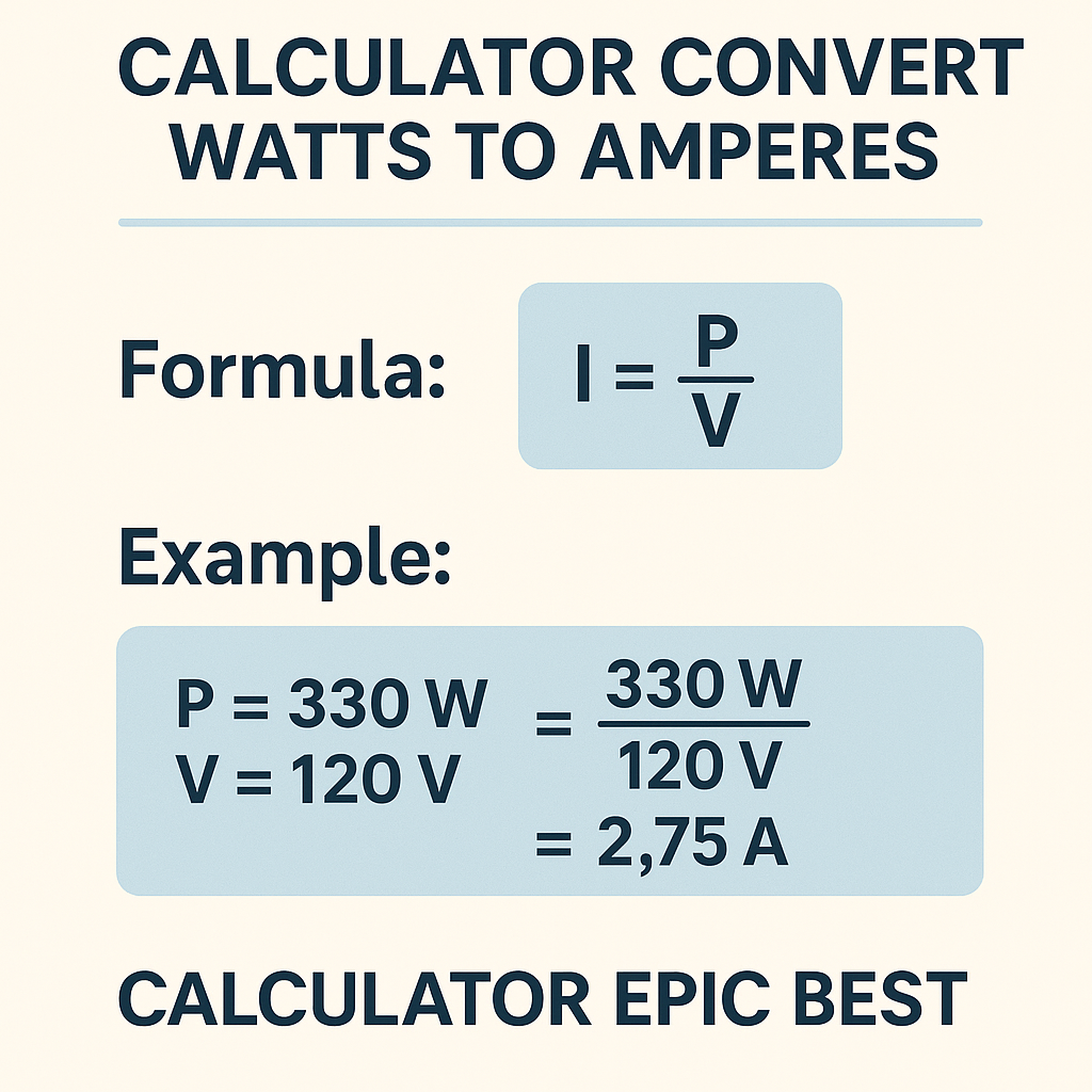
Basic DC and single-phase resistive formula
Variables:
- P — Real power, in watts (W).
- V — Voltage across the load, in volts (V).
- I — Current through the load, in amperes (A).
- Household mains: 120 V (North America) or 230 V (Europe).
- Small appliance power: 100 W to 3 000 W.
Single-phase AC with non-unity power factor
When the load is not purely resistive (motors, transformers, fluorescent lighting), the current depends on the power factor (PF).
Variables:
- PF — Power factor (dimensionless), typically between 0.6 and 1.0 for many loads. Inductive motors often 0.7–0.95 depending on load and compensation.
- Other variables as above.
- Incandescent lamps: PF ≈ 1.0
- Single-phase small motors: PF ≈ 0.7–0.9
- Large induction motors: PF ≈ 0.8–0.95 (depending on loading)
Three-phase AC systems
In three-phase systems the conversion accounts for √3 (≈1.732) when voltages are line-to-line.
Variables:
- P — Total real power consumed by the three-phase load (W).
- V_LL — Line-to-line voltage (V), typical industrial values: 400 V (Europe), 480 V (North America industrial), 600 V.
- PF — Power factor of the load.
- I — Line current per phase (A).
- Small industrial motors: 3.7 kW to 22 kW.
- Medium loads: tens to hundreds of kW.
Apparent power and reactive components: measuring and converting
Apparent power S (in volt-amperes, VA) relates voltage and current irrespective of power factor. Keeping S in calculations avoids confusion when PF<1.
Relationship with real power P and reactive power Q:
- P = S × PF
- Q = S × sin φ where φ is the phase angle and PF = cos φ
- S — Apparent power in VA.
- Q — Reactive power in VAR (volt-ampere reactive).
- φ — Phase angle between voltage and current.
Extensive tables with common conversions
| Load | Typical Power (W) | Current @120 V (A) | Current @230 V (A) |
|---|---|---|---|
| LED lamp | 10 | 0.083 | 0.043 |
| Phone charger | 12 | 0.100 | 0.052 |
| Desktop PC | 300 | 2.50 | 1.30 |
| Microwave oven | 1,000 | 8.33 | 4.35 |
| Hair dryer | 1,500 | 12.50 | 6.52 |
| Water kettle | 3,000 | 25.00 | 13.04 |
| Space heater | 4,000 | 33.33 | 17.39 |
| Power (kW) | Voltage (V_LL) | PF | Calculated Current (A) |
|---|---|---|---|
| 5 | 400 | 0.85 | 8.49 |
| 11 | 400 | 0.85 | 18.69 |
| 22 | 400 | 0.85 | 37.38 |
| 50 | 415 | 0.85 | 82.52 |
| 100 | 480 | 0.85 | 142.06 |
Detailed derivation of formulas and variable definitions
Derivation for DC and single-phase resistive loads
Starting from the definition of power for resistive loads:
Rearrange to calculate current:
Where:
- P is the power drawn by the device (W).
- V is the voltage across the device (V).
- I is the resulting current (A).
Accounting for power factor in AC circuits
Real power in AC circuits is the product of apparent power and power factor:
Rearrange:
Note: Use the measured power factor (or manufacturer rated PF) for precise results. For conservative sizing, assume lower PF.
Three-phase derivation
For balanced three-phase systems, total real power is:
Thus:
Where √3 ≈ 1.732. Use line-to-line voltage for V_LL when loads are connected in star or delta and current measured per phase.
Best-practice calculator workflow and UX considerations
When creating or using a power-to-current calculator, follow an explicit workflow for clarity and safety:
- Specify system type: DC, single-phase AC, or three-phase AC.
- Enter measured or nominal voltage (V). Distinguish between line-to-neutral and line-to-line for three-phase.
- Enter real active power (P) in watts. If only VA is available, note PF to compute real power.
- Enter power factor (PF) for AC loads; provide sensible defaults with the option to override.
- Present results with recommended rounding and unit suffixes; provide recommended protective device ratings.
Additional UX features:
- Inline help icons explaining PF, apparent power, and continuous vs non-continuous loads.
- Option to toggle units (W, kW) and voltages (V).
- Warnings when calculated current exceeds typical breaker or cable ampacities.
Examples with full development and detailed solutions
Example 1 — Single-phase household appliance
Problem: Determine the current drawn by a 1,800 W space heater connected to a 230 V household supply. Assume purely resistive load (PF = 1). Then show recommended protective device selection.
Step 1 — Identify variables:
- P = 1,800 W
- V = 230 V
- PF = 1.0 (resistive)
Calculate numeric value: I ≈ 7.826 A
Step 3 — Interpret results for protective device selection:
- Round up final operating current for continuous loads per common wiring practices. For continuous resistive heating (continuous >3 hours), many codes require sizing at 125% of continuous current. So design current = 7.826 × 1.25 ≈ 9.78 A.
- Choose standard circuit breaker rating: nearest common standard is 10 A or 13 A depending on region. Select 10 A for precise circuit or 13 A for conservative approach if allowed by local regulations.
- Cable sizing: check ampacity tables per local code. For example, a 1.5 mm² copper conductor might be rated 10–16 A depending on installation method and temperature. Confirm with the applicable code and derating factors.
Key takeaways:
- Calculated current is ~7.83 A; design with 125% factor for continuous duty = ~9.78 A.
- Select protective device and conductor based on local regulations and derating factors.
Example 2 — Three-phase motor load with power factor and efficiency
Problem: A three-phase induction motor has a nameplate of 22 kW output (mechanical). Motor efficiency η = 0.93 and power factor PF = 0.88 at rated load. Supply voltage is 400 V line-to-line. Determine the electrical input current per phase.
Step 1 — Compute electrical input power P_in from mechanical output:
- P_out = 22,000 W
- η = 0.93 => P_in = P_out / η = 22,000 / 0.93
Calculate P_in: P_in ≈ 23,655.91 W (rounded to 23.656 kW)
Step 2 — Apply three-phase current formula:
Now compute denominator:
- 1.732 × 400 = 692.8
- 692.8 × 0.88 ≈ 609.664
So I ≈ 23,655.91 / 609.664 ≈ 38.79 A
Step 3 — Apply safety and code multipliers:
- Motors often have inrush currents several times rated current. Select motor starters and protection devices per local code and manufacturer starting current.
- For continuous operation, check if continuous sizing factors apply; consult standards (e.g., NEC or IEC) for conductor and breaker sizing for motors. Example: if 125% rule or service factor applies, multiply rated full-load current accordingly when selecting conductor and overcurrent protection.
- Rounded design current (for conductor ampacity) might be 38.79 × 1.25 ≈ 48.49 A; choose a cable and breaker consistent with local electrical code (e.g., 50 A breaker and appropriate conductor cross-section after derating).
Summary of solved values:
- Electrical input power P_in ≈ 23.656 kW
- Calculated line current ≈ 38.8 A
- Design conductor/breaker selection must consider inrush, code ampacity rules, and derating.
Edge cases, limitations, and measurement accuracy
Be aware of several practical considerations when converting watts to amperes:
- Power factor variability: PF depends on load and load condition. Using a single assumed PF can lead to under- or over-sizing.
- Transient and inrush currents: Motors, compressors, and inductive loads have large starting currents; sizing of switches, contactors, and fuses must account for these peaks.
- Harmonics: Non-linear loads (variable frequency drives, rectifiers, LED drivers) distort waveform; apparent current includes harmonic components that affect cable heating and protective devices.
- Temperature and installation conditions: Cable ampacity changes with ambient temperature, grouping, and installation method; always consult local ampacity tables and apply derating.
- Measurement method: Real measured power (via wattmeter or power analyzer) and true RMS current measurement give the best data for conversions.
Regulatory references and authoritative standards
Key standards and normative references to consult when designing and verifying electrical installations and when interpreting load currents:
- IEC 60364 — Electrical installations of buildings (International Electrotechnical Commission): https://www.iec.ch/
- NFPA 70 (NEC) — National Electrical Code (United States): https://www.nfpa.org/nec
- IEEE standards relevant to power measurement and harmonics: https://www.ieee.org/
- BS 7671 — Requirements for Electrical Installations (IET Wiring Regulations, United Kingdom): https://www.theiet.org/
- Local utility and grid codes for connection and protection rules (consult your local service provider).
When designing or applying the results of calculations, always cross-reference the appropriate code and standards for your jurisdiction. For example, the NEC contains specific rules for motor branch-circuit sizing and continuous loads; IEC standards address conductor selection and protective device characteristics in international practice.
Advanced topics: harmonic currents, true RMS, and power quality implications
Conversion formulas assume sinusoidal voltage and current with a single power factor term. Real modern systems often include non-linear loads that generate harmonics; these cause:
- Increased heating in conductors and transformers beyond what fundamental current alone predicts.
- Misleading power factor readings if only using displacement power factor; true power factor includes harmonic effects.
- Requirement for true RMS instruments and power analyzers to correctly measure current and power.
Recommended actions for harmonic-rich environments:
- Specify true RMS meters and data logging for commissioning.
- Consider oversizing transformers and conductors based on harmonic distortion and manufacturer guidance.
- Apply harmonic mitigation (filters, active front-end drives) where necessary to meet utility connection requirements.
Practical checklist for engineers and electricians using converters or calculators
- Confirm supply type (DC, single-phase AC, three-phase AC) and correct voltage reference.
- Use measured real power (kW) where available. If only apparent power (kVA) is known, convert using PF.
- Input actual PF measured or specified by manufacturer; when unknown, use conservative PF values appropriate to load type.
- Adjust for continuous load multipliers required by the local electrical code.
- Include allowances for harmonic content, inrush currents, and ambient or grouping derating when selecting protective devices and conductors.
- Document assumptions (PF, efficiency, duty cycle) and include them in calculations and reports for auditability.
Conversion quick reference formulas
Single-phase resistive:
Single-phase AC with PF:
Three-phase balanced system:
Apparent power relations:
Sources, further reading, and useful external links
Authoritative documents and web resources for design, verification, and regulatory compliance:
- IEC official portal (standards search and purchase): https://www.iec.ch/
- NFPA (National Fire Protection Association) NEC resources and code subscription: https://www.nfpa.org/nec
- IEEE Xplore Digital Library for technical papers on power quality and harmonics: https://ieeexplore.ieee.org/
- IET (Institution of Engineering and Technology) for information on BS 7671 and wiring regulations: https://electrical.theiet.org/
- European Committee for Electrotechnical Standardization (CENELEC) — regional standards references and harmonization: https://www.cencenelec.eu/
Final recommendations for implementing a high-quality watts-to-amperes calculator
To build the epic best calculator for converting watts to amperes, ensure the tool provides:
- Clear selection between DC, single-phase, and three-phase modes.
- Fields for PF and efficiency, with default suggested values and explanations.
- Automatic unit normalization and rounding rules for human-readable results.
- Advisories for code-specific multipliers (continuous loads, motor starting) and links to standard references.
- Exportable calculation report showing inputs, formulas used, intermediate steps, and references for compliance documentation.
When in doubt, measure actual power with appropriate instruments and consult the applicable codes (NEC, IEC, BS 7671, or local standards) to validate protection and conductor sizing. Proper documentation of assumptions and margins will ensure safe, auditable electrical designs that withstand inspection and real-world use.