This article details methods to calculate arc flash boundaries using incident energy thresholds precisely and
Engineers require clear, code-compliant procedures with calculations, examples, and normative references included for safety verification
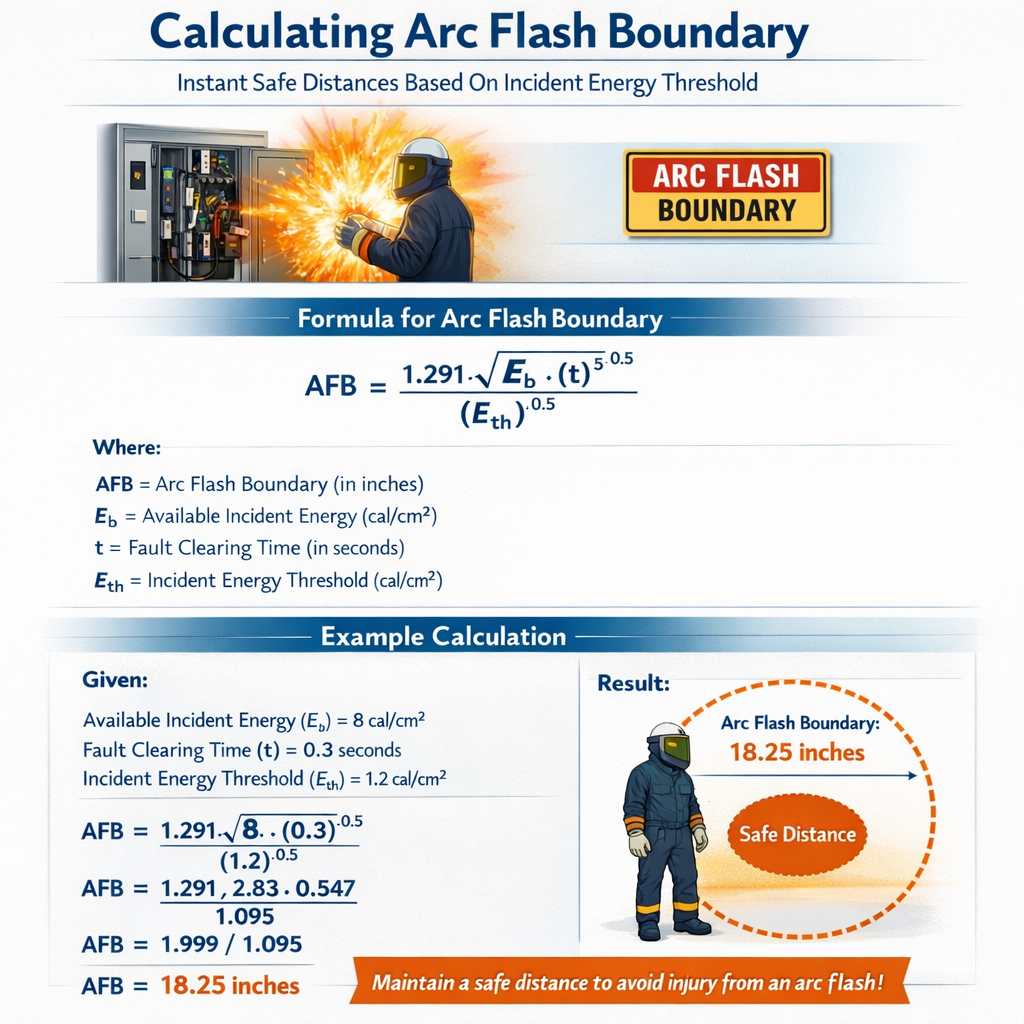
Arc Flash Boundary Calculator Based on Incident Energy Threshold (Instant Safe Distance)
Scope and purpose of instant safe distance calculations
Arc flash boundary calculations define the minimum safe stand-off distance where incident energy is below a chosen damage or injury threshold. This article provides a systematic, reproducible method to compute arc flash boundary distances instantly from incident energy thresholds, using empirical equations, inverse-distance scaling, and conservative assumptions familiar to practicing engineers.This guidance aligns with NFPA 70E and IEEE 1584 methodologies while providing simplified closed-form formulas that permit rapid “instant” evaluation and verification in design, field audits, and safety planning. The approach emphasizes traceable inputs, clear definitions, and worked examples suitable for technical reports and compliance documentation.Fundamental concepts and governing relationships
Incident energy and arc flash boundary definition
Incident energy (E) is the thermal energy per unit area (cal/cm2 or J/cm2) received by a surface at a given distance from an arcing fault during the arc duration. The arc flash boundary (AFB) for an incident energy threshold E_thr is the radial distance r_E such that:At distance r = r_E, incident energy E(r_E) = E_thr
Scaling relationship and simplified inverse-square model
For rapid calculations an inverse-square radiation approximation is widely used as a conservative estimator of spatial decay of incident energy. Under an inverse-square assumption, incident energy scales approximately with 1/r2 for far-field radiation from a localized source. We express incident energy at distance r as:E(r) = C * I_arc2 * t / r2
Where:- C is an empirical coefficient that consolidates geometry, emissivity, and unit conversions.
- I_arc is the arcing current (kA).
- t is the arc duration (s), typically the clearing time of overcurrent protection.
- r is the distance (cm or m) from the arc to the target surface.
r_E = sqrt( C * I_arc2 * t / E_thr )
r_E = I_arc * sqrt( C * t / E_thr )
Meaning and recommended values for variables
Explain each variable and provide typical values used in practice:- I_arc: Arcing current magnitude (kA). Typical range: 0.5 kA (low fault, small enclosure) to >40 kA (high fault medium voltage). Field-value estimation methods include bolted-fault calculations and IEEE 1584 empirical arcing current models.
- t: Arc duration (s). Usually the fuse or breaker clearing time. Typical values: 0.035 s (35 ms) for fast tripping breakers with short-circuit detection, 0.1–0.5 s for slower clearing devices, up to several seconds for failed protection scenarios.
- E_thr: Incident energy threshold (cal/cm2). Common thresholds: 1.2 cal/cm2 (onset of second-degree burn), 4 cal/cm2, 8 cal/cm2, 40 cal/cm2 (extreme hazard). These are used for PPE selection per NFPA 70E.
- C: Empirical constant (units such that equation yields incident energy in cal/cm2 when I_arc in kA, t in seconds, r in cm). Typical C values depend on equipment geometry and enclosure; see table below.
Recommended empirical constants and lookup values
Below are practical values of the empirical constant C and equivalent consolidated constant k that allow the formula to be used with conventional units. Use these as conservative defaults when detailed IEEE 1584 calculations are unavailable.| Equipment scenario | Typical arcing geometry | Representative C (cal·cm2/kA2/s) | Alternate consolidated k (cm/kA·√s/cal1/2) | Comments |
|---|---|---|---|---|
| Open bus, low voltage (480 V) | Unprotected open conductor | 0.020 | 4.47 | High radiation, close-in exposure; conservative |
| Bolted bus inside panel (480 V) | Small access opening, partial enclosure | 0.012 | 3.46 | Common on switchgear and panelboards |
| Large switchgear enclosed (MV) | Fully enclosed compartment | 0.006 | 2.45 | Enclosures reduce radiative coupling; conservative |
| Medium-voltage air switch, outdoor | Open air across gap | 0.025 | 5.00 | High energy, high arcing currents typical |
| Typical field conservative default | Use when geometry uncertain | 0.015 | 3.87 | Widely used fallback for screening calculations |
Unit consistency and conversion guidance
Ensure unit consistency: If you use I_arc in kA, t in seconds, and desire E in cal/cm2, choose C accordingly. The tables above assume those units. If you prefer SI units (J/cm2 or J/m2), convert using 1 cal = 4.184 J and adjust C accordingly.Common incident energy thresholds and PPE mapping
| Incident Energy (cal/cm2) | Typical PPE recommendation | PPE example | Typical safe boundary implications |
|---|---|---|---|
| ≤ 1.2 | Minimal risk; basic arc-rated PPE | Arc-rated clothing 4 cal/cm2 | Shorter boundary; work permitted with basic PPE |
| 1.2 – 4 | Moderate risk; standard arc-rated PPE | Arc suit 8 cal/cm2 | Increased boundary; limit exposure and use PPE |
| 4 – 8 | High risk; full arc-rated PPE | Arc suit 8–12 cal/cm2, face shield | Keep personnel outside unless essential with full PPE |
| > 40 | Extreme hazard; avoid proximity | Specialized arc flash mitigation; incident excluded | Consider lockout/tagout and equipment modification |
Step-by-step procedure to compute an instant arc flash boundary
Follow these steps to calculate r_E quickly for field verification or design documentation.- Determine the available arcing current I_arc (kA). Use measured fault current, bolted-fault estimate, or IEEE 1584 arcing current model.
- Determine arc duration t (s). Use protective device let-through time, including upstream breakers or fuse clearing times at the estimated arcing current.
- Select the target incident energy threshold E_thr (cal/cm2) that defines the safe distance; e.g., 1.2 cal/cm2 for minimal second-degree burn threshold or employer-specified PPE threshold.
- Select a conservative C value appropriate to the equipment scenario from the table above. If uncertain, use the field conservative default C = 0.015.
- Compute r_E using r_E = sqrt( C * I_arc2 * t / E_thr ). Ensure consistent units (I_arc in kA, t in s, E_thr in cal/cm2).
- Document assumptions, protection timings, and sources; apply rounding up to the nearest practical distance for field safety.
Worked examples — full development and solutions
At least two real-case examples with detailed steps are provided. Each illustrates a different scenario and validates the approach against practical parameters.Example 1 — Low-voltage panelboard, 480 V feeder, typical maintenance access
Scenario: A maintenance technician will work at the front of a 480 V panelboard. Determine the arc flash boundary for an incident energy threshold of 1.2 cal/cm2 using conservative assumptions.Given:- Estimated arcing current, I_arc = 8 kA (typical bolted-fault portion and arcing fraction)
- Protective device clearing time, t = 0.08 s (80 ms) — typical for instantaneous trip of a molded-case breaker
- Threshold, E_thr = 1.2 cal/cm2
- Conservative C for bolted bus inside panel, from table: C = 0.012 (cal·cm2/kA2/s)
r_E = sqrt( C * I_arc2 * t / E_thr )
Compute intermediate values:- I_arc2 = (8 kA)2 = 64 kA2
- Numerator = C * I_arc2 * t = 0.012 * 64 * 0.08
- Numerator calculation: 0.012 * 64 = 0.768; 0.768 * 0.08 = 0.06144
- r_E = sqrt( 0.06144 / 1.2 ) = sqrt( 0.0512 )
- r_E = 0.2263 (units: cm? Confirm units below)
- r_E (cm) = 0.2263 cm → r_E (m) = 0.002263 m
From table, consolidated k = 3.46 (cm / (kA·√(s/cal))). Use r_E = k * I_arc * sqrt( t / E_thr ).
Compute:- sqrt( t / E_thr ) = sqrt( 0.08 / 1.2 ) = sqrt( 0.0666667 ) = 0.2582
- r_E = 3.46 * 8 * 0.2582 = 3.46 * 2.0656 = 7.15 cm
- r_E in meters = 0.0715 m ≈ 72 mm
Example 2 — Medium-voltage outdoor switch, 15 kV, fault current high
Scenario: Field crew near a 15 kV outdoor air-insulated switch. Estimate the arc flash boundary for a threshold of 4 cal/cm2 (common PPE threshold) using conservative parameters.Given:- Estimated arcing current, I_arc = 20 kA (high available fault)
- Protective device clearing time, t = 0.12 s (120 ms)
- Threshold, E_thr = 4 cal/cm2
- Conservative C for medium-voltage open air, from table: C = 0.025
r_E = k * I_arc * sqrt( t / E_thr )
- t / E_thr = 0.12 / 4 = 0.03
- sqrt(0.03) = 0.173205
- r_E = 5.00 * 20 * 0.173205 = 5 * 20 * 0.173205 = 100 * 0.173205 = 17.3205 cm
- r_E in meters = 0.1732 m ≈ 0.17 m
Practical considerations and conservative factors
When applying instant calculations in the field, consider these items:- Use worst-case protective device clearing times (longer times increase incident energy and extend the AFB).
- When arcing current is uncertain, use the upper bound available fault current or modeled arcing current from IEEE 1584.
- Enclosures, doors, and shields reduce incident energy; if present, use a lower C value appropriate to enclosure protection.
- For tasks involving face/eye exposure, consider additional standoff margin beyond the computed r_E to account for projection and non-radiative effects.
- Round distances up to the nearest practical increment (e.g., 0.1 m) for signage and procedural clarity.
When to use detailed IEEE 1584 calculations
Use simplified inverse-square based instant calculations for rapid screening, design orientation, or field verification. For final design, high-risk situations, or where legal compliance and detailed documentation are required, perform full IEEE 1584-2018 or IEC 61482-1-1 calculations which consider:- Voltage, gap, electrode geometry, and grounding factors
- Empirical arcing current prediction
- Enclosure size and opening area
- Multiple protection device characteristics and coordination
Example validation against IEEE 1584 principles
IEEE 1584-2018 provides empirical models to compute incident energy for specific electrode configurations, enclosure sizes, and voltage classes. While those models are more complex, their computed incident energy curves generally follow an approximately 1/r2 trend at distances beyond the near-field; therefore, the inverse-square screening formula used here is acceptable for conservative, quick evaluations. Always document when you used a screening method rather than a full standard-compliant model.Documentation and reporting best practices
When producing a report or safety permit showing instant arc flash boundary values, include:- All input data: source fault current, arcing current estimation method, protective device curves, and clearing times.
- Selected C or k constant and justification (geometry photographs or drawings help).
- Threshold E_thr and PPE policy mapping.
- Step-by-step calculation, units, and numeric intermediate values.
- Conservative rounding and administrative controls applied.
- References to standards used and version numbers.
Regulatory and normative references
Cite and consult the following authoritative standards and documents for detailed, code-compliant practices:- IEEE 1584-2018, “IEEE Guide for Performing Arc-Flash Hazard Calculations.” URL: https://standards.ieee.org/standard/1584-2018.html
- NFPA 70E, “Standard for Electrical Safety in the Workplace.” URL: https://www.nfpa.org/codes-and-standards/all-codes-and-standards/list-of-codes-and-standards/detail?code=70E
- IEC 61482-1-1, “Protective clothing against the thermal hazards of an electric arc.” URL: https://www.iso.org/standard/57055.html (IEC standards accessible via ISO/IEC catalog)
- Occupational Safety and Health Administration (OSHA) directives relevant to electrical safety. URL: https://www.osha.gov/electrical
Limitations and recommended next steps
The instant method presented is a conservative screening tool and is not a substitute for full standard-based calculations where required. Limitations include:- Empirical constant C depends on geometry; misuse can underestimate or overestimate energy.
- Inverse-square assumption may not hold in near-field or within confined enclosures with reflecting surfaces.
- Does not capture fragmentation hazards, pressure waves, or metal vapor effects from high-energy MV arcs.
- For critical assets, perform IEEE 1584-2018 calculations with validated software.
- Measure fault current and verify protection coordination to obtain realistic t and I_arc values.
- Apply PPE, barrier, and administrative controls based on conservative engineering judgment and company policy.
Summary of actionable formulas and quick-reference table
Key formulas for instant computation:Incident energy at distance r: E(r) = C * I_arc2 * t / r2
Arc flash boundary for threshold E_thr: r_E = sqrt( C * I_arc2 * t / E_thr )
Alternate consolidated form: r_E = k * I_arc * sqrt( t / E_thr ), where k = sqrt(C) with units adjusted
| Parameter | Unit | Typical range | Recommended default for screening |
|---|---|---|---|
| I_arc | kA | 0.5 – 40+ | Use measured or bolted-fault estimate |
| t | s | 0.03 – 2.0 | Use protective device clearing time; if unknown use 0.1 s |
| E_thr | cal/cm2 | 1.2 – 40 | 1.2 cal/cm2 for minimum safety criterion |
| C | cal·cm2/kA2/s | 0.006 – 0.025 | 0.015 as conservative default |
| k | cm / (kA·√(s/cal)) | 2.45 – 5.00 | 3.87 as conservative default |
Further reading and tools
For comprehensive design and compliance use:- IEEE 1584 calculation tools and verified commercial software (e.g., ETAP, SKM PowerTools) that implement the full empirical model and provide enclosure corrections.
- NFPA 70E guidance and calculator worksheets for job briefings and PPE selection.
- Manufacturer technical bulletins on arc-resistant switchgear and engineered mitigation solutions.
- IEEE 1584-2018 guide: https://standards.ieee.org/standard/1584-2018.html
- NFPA 70E: https://www.nfpa.org/codes-and-standards/all-codes-and-standards/list-of-codes-and-standards/detail?code=70E
- IEC 61482: refer to IEC webstore or national adoption documents for test method details
- OSHA electrical safety information: https://www.osha.gov/electrical