Rapid, accurate OCPD screening for buck‑boost transformers ensures safe, code‑compliant primary protection and efficient sizing.
This article presents calculator methodology, step‑by‑step examples, precise formulas, and deterministic selection guidance for engineers.
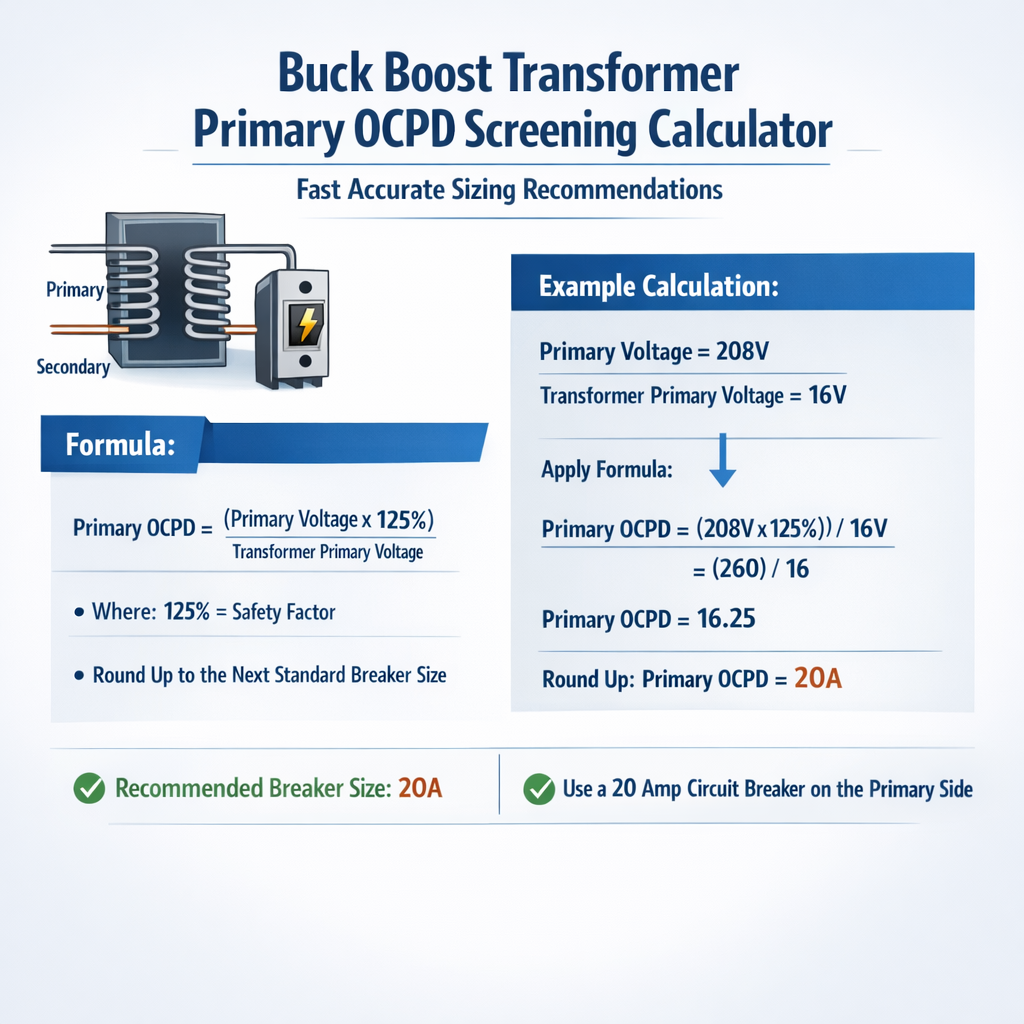
Buck-Boost Transformer Primary OCPD Screening Calculator (Recommended Primary Overcurrent Device Rating)
Scope, intent, and engineering constraints
Buck‑boost transformers are small specialty transformers used for minor voltage corrections, often rated from a few hundred VA to several kVA. The primary overcurrent protective device (OCPD) must protect conductors and equipment while allowing for magnetizing inrush and acceptable operation under normal and fault conditions. This article covers: calculation methods for primary full‑load current; short‑circuit screening; transformer impedance effects; practical fuse and breaker recommendations; and two worked examples with documentation of assumptions. Key engineering constraints include:- Transformer kVA rating and primary nominal voltage
- Available fault current at the transformer primary (source short‑circuit capacity)
- Transformer percent impedance (Z%) and magnetizing inrush characteristics
- Applicable code and standards (NEC/NFPA, IEEE, UL, IEC)
- Coordination with secondary protection and load characteristics
Fundamental electrical relationships and formulas
Below are the fundamental formulas used by the screening calculator. All formulas are presented using plain HTML math expressions. Each variable is defined and typical values are provided.Single‑phase full‑load primary current:
- I_pri_FL = full‑load primary current (A)
- kVA = transformer rating in kilovolt‑amperes (kVA)
- V_pri = primary nominal voltage (V)
- Typical values: kVA = 0.5, 1, 2.5, 5; V_pri = 120, 208, 240, 277
Three‑phase full‑load primary current:
- sqrt(3) is approximately 1.732
- Typical three‑phase kVA for buck‑boost style correction is uncommon but the formula applies to small 3‑phase units
Transformer short‑circuit (secondary) available fault current (approximate using Z%):
I_sc_secondary ≈ I_sec_FL × (100 / Z%)
- I_sc_secondary = approximate symmetrical short‑circuit current at secondary rated voltage (A)
- I_sec_FL = secondary full‑load current = (kVA × 1000) / V_sec (A)
- Z% = transformer percent impedance (typically 2%–8% for small units)
- Example typical Z%: 2.5% (low impedance), 4% (medium), 6% (higher)
Primary short‑circuit current (approximate) when neglecting source impedance:
I_sc_primary ≈ I_pri_FL × (100 / Z%)
- Note: Real available primary fault current will be limited by source impedance; always perform full source‑plus‑transformer short‑circuit calculation where possible.
Transformer turns ratio (ideal):
- N = turns ratio (unitless)
- Used for reflecting impedances between primary and secondary by multiplying impedance by N^2
- Reference for complex coordination tasks
Typical magnetizing inrush and its impact on OCPD selection
Magnetizing inrush for small buck‑boost transformers is often large in amplitude (several times full‑load current) but short in duration (tens of milliseconds). Inrush magnitude depends on residual flux, switching instant, and core design. Typical inrush multipliers:- Small closed‑core single‑phase: 5× to 10× FL current
- Window‑type small transformers: 3× to 7× FL current
- Engineering practice: use time‑delay fuses or inverse‑time breakers to ride through inrush
Code references, standards, and normative guidance
Relevant authoritative sources:- NFPA 70, National Electrical Code (NEC), Article 450 — Transformers and Transformer Vaults: https://www.nfpa.org/ (search NEC Article 450)
- NEC Article 240 — Overcurrent Protection: https://www.nfpa.org/ (search NEC Article 240)
- IEEE Std C57.12 family — Standard for Power Transformers: https://standards.ieee.org/
- IEC 60076 — Power Transformers: https://www.iec.ch/standards
- UL 1561 and UL 507 (as applicable for specific transformer/fuse assembly and components): https://www.ul.com/
- NEMA and manufacturer data for inrush and Z% typical values: https://www.nema.org/
Screening algorithm overview for a buck‑boost primary OCPD calculator
A practical calculator uses the following sequential checks:- Compute full‑load primary current using the appropriate formula for single‑ or three‑phase.
- Determine whether load is continuous per NEC definitions (continuous = 3 hours or more) and apply continuous load multiplier if required for conductor ampacity and OCPD selection.
- Assess magnetizing inrush and assign an inrush multiplier or select an inrush‑tolerant protective class. Flag devices that would nuisance‑trip at inrush current.
- Estimate available source short‑circuit current at the transformer primary (get from utility or site study). If not available, use conservative source impedance models or look‑up tables for typical service sizes.
- Compute transformer prospective fault current based on Z% and source impedance; ensure selected OCPD interrupting rating (ICU) and trip characteristics are compatible.
- Recommend OCPD type and size: suggested fuse class (time‑delay, class RR, RK1, J, T) or breaker curve (inverse time, thermal magnetic) and percentage of FL current for pickup.
- Output final recommended device rating, minimum interrupting capacity, and notes about coordination and installation (e.g., fuse or breaker in primary only vs. secondary protection needed).
Practical selection heuristics used by the calculator
- For small buck‑boost single‑phase units (≤1 kVA): recommend primary fusing at 150% of FL for non‑continuous loads if using time‑delay fuses; for continuous loads, size per NEC conductor rules and likely fuse at 125%–150% depending on manufacturer guidance.
- For kVA >1 and ≤5 kVA: recommend time‑delay fuses or inverse‑time breakers with pickup at 125%–200% of FL depending on inrush and secondary coordination.
- If available primary fault current is low (<5× FL) and Z% moderate (>4%), a fast‑acting device may be acceptable; if available fault current is high (>10× FL), ensure OCPD interrupting rating matches prospective fault current.
- Always prefer protective devices with coordination curves published by the manufacturer to plan selective coordination between primary and downstream devices.
Extensive common values table
| kVA | Primary V | Secondary V | Primary FL Current (A) | Typical Z% | Estimated Inrush (×FL) | Recommended OCPD Type |
|---|---|---|---|---|---|---|
| 0.25 | 120 | 110 | 2.08 | 4–8 | 3–6 | Time‑delay fuse (small slow‑blow) |
| 0.5 | 240 | 230 | 2.08 | 3–6 | 4–8 | Time‑delay fuse, Class J or RK, small ampere |
| 1 | 240 | 230 | 4.17 | 3–5 | 4–8 | Time‑delay fuse Class RK1/J or inverse breaker |
| 2.5 | 240 | 230 | 10.42 | 2.5–5 | 5–10 | RK1/J fuses or thermal‑magnetic breaker |
| 5 | 240 | 230 | 20.83 | 2.5–4 | 5–10 | RK1 fuses, breaker with adjustable trip |
| 10 | 240 | 230 | 41.67 | 2–4 | 6–12 | Industrial time‑delay fuse or breaker |
Interrupting capacity and short‑circuit coordination
Select an OCPD with an interrupting rating (ICU) equal to or greater than the highest prospective fault current at the installation point. Typical small buck‑boost installations on low‑voltage services may experience utility fault levels from a few kiloamperes up to tens of kiloamperes. Always request the utility available fault current at the service point.Approximate primary prospective fault current from transformer only (no source impedance):
I_sc_primary ≈ I_pri_FL × (100 / Z%)
- Example: 1 kVA, 240 V, I_pri_FL = 4.167 A, Z% = 4% → I_sc_primary ≈ 4.167 × (100/4) = 104.17 A
- This is only the transformer's contribution; the source may contribute far more or limit the current depending on service impedance.
Recommended ranking of fuse classes for buck‑boost primaries
- Class J or RK1 time‑delay fuses: good balance of inrush tolerance and clearing capability for 1–10 kVA
- Class T slow‑blow fuses: common for small transformers and motor circuits with high inrush
- Class HRC (high rupturing capacity) fuses: use where high short‑circuit capacity expected
- Thermal magnetic breakers (adjustable): useful when coordination or adjustable long‑time delay is needed
Example 1 — Single‑phase 1 kVA buck‑boost primary OCPD screening
Scenario assumptions:- Transformer rating: 1.0 kVA single‑phase
- Primary nominal voltage: 240 V
- Secondary nominal voltage: 230 V (buck‑boost correction)
- Load: non‑continuous resistive lighting, ≤1 kVA
- Transformer percent impedance (manufacturer data): Z% = 4%
- Utility available fault current at primary: 5 kA (5000 A)
- Compute primary full‑load current:
I_pri_FL = (1.0 × 1000) / 240 = 4.1667 A
- Estimate transformer short‑circuit contribution (transformer only approximation):
I_sc_primary ≈ 4.1667 × (100 / 4) = 104.17 A
- Assess source available fault current: 5000 A at primary (dominant). Therefore, the selected OCPD must have an interrupting rating ≥5000 A.
- Inrush consideration:
Assume inrush multiplier = 6× → inrush current ≈ 6 × 4.167 = 25 A (short duration)
- Device selection heuristics:
- FL = 4.17 A; inrush ~25 A. Use time‑delay fuse sized to allow inrush but protect conductors.
- Recommended fuse sizing: choose a fuse with ampere rating such that it does not blow at repeated inrush events but will clear sustained overloads. Typical choice: slow‑blow fuse rated 150% of FL for non‑continuous loads = 1.5 × 4.17 ≈ 6.25 A → choose nearest commercial size 7 A slow‑blow (Class J or Class T rated for 5 kA interrupting).
- Confirm interrupting rating: choose a 10 kAIC or greater fuse or fuse holder rated to at least 5 kA (preferably 10 kA for margin).
- Final recommendation:
- Primary OCPD: 7 A slow‑blow (Class J or Class T), minimum interrupting rating 10 kAIC
- Notes: Verify conductor ampacity for 7 A fuse; if conductors are small (e.g., 14 AWG), verify NEC conductor sizing and continuous load rules. Consult manufacturer for exact fuse selection.
Example 2 — Three‑phase equivalent small unit and coordination with upstream breaker
Scenario:- Converter application uses a 5 kVA three‑phase buck‑boost style correction transformer (rare but possible in small three‑phase equipment)
- Primary voltage: 240 V three‑phase
- Transformer Z% (manufacturer): 3%
- Primary service: 225 A breaker upstream with available fault current of 25 kA at the service
- Load: continuous balanced load drawing 80% of transformer kVA
- Compute three‑phase primary full‑load current:
I_pri_FL = (5 × 1000) / (240 × 1.732) = 5000 / 415.68 = 12.03 A
- Determine continuous load current:
Continuous load = 0.8 × kVA = 4.0 kVA → I_load = (4000) / (240 × 1.732) = 9.627 A
For continuous loading, NEC may require sizing OCPD/conductors for 125% of continuous current; therefore design current to protect is 1.25 × 9.627 = 12.034 A (same as FL roughly). - Transformer contribution to primary short‑circuit (approximate):
I_sc_primary ≈ I_pri_FL × (100 / Z%) = 12.03 × (100 / 3) ≈ 401 A
- Source available fault current: 25 kA — this will be the governing interrupting rating for all devices upstream; the OCPD must be rated for the available fault level or be installed behind devices with adequate interrupting capability.
- Inrush estimate: assume inrush multiplier 8× for this core design → inrush ≈ 96 A (very short duration). The primary OCPD must ride through this peak without nuisance tripping.
- Device selection:
- A standard thermal‑magnetic breaker with adjustable long‑time (or electronic) trip could be set to pick up at 125% of continuous design current: pickup ≈ 1.25 × 12.03 ≈ 15 A. Select a breaker with long‑time delay that withstands 96 A inrush transient of milliseconds. Alternatively, use RK‑type time‑delay fuses sized at 150%–200% of FL (e.g., 20 A slow‑blow) with minimum interrupting rating 25 kAIC.
- Because inrush is 96 A and long‑time delay can survive short bursts, a breaker with an inverse curve and adjustable instantaneous trip set above 200 A would likely not trip on inrush.
- Final recommendation:
- Primary OCPD: 20 A time‑delay RK1 fuse or 15 A adjustable thermal‑magnetic breaker with instantaneous trip set >200 A
- Minimum interrupting rating: 25 kAIC (match utility available fault)
- Coordination: verify that upstream 225 A breaker has appropriate coordination with the chosen upstream devices to maintain selectivity
Practical cautions, field checks, and measurement tips
- Always obtain transformer nameplate data: kVA rating, primary/secondary voltages, percent impedance (Z%), inrush characteristics if provided, and recommended primary protection from manufacturer.
- Obtain utility available fault current at the point of connection; do not assume transformer alone limits the fault current unless proven by system impedance calculations.
- If inrush or nuisance trips are observed during commissioning, use time‑delay fuses or adjust breaker time‑current settings; do not increase protective device rating beyond conductor ampacity limits.
- For circuit conductor compliance, apply NEC conductor ampacity rules and continuous load multipliers where applicable.
- Document assumptions (Z%, inrush multiplier, service fault current) and keep calculations with the equipment records for maintenance and AHJ review.
When to use a protector on the secondary versus the primary
Primary protection prevents damage to conductors and provides disconnect for the transformer in the event of internal faults or external faults on the primary. Secondary protection is required when the secondary conductors or loads need protection and may be sized differently. Often both are used:- Primary OCPD protects the transformer and primary conductors; must have adequate interrupting rating and ride‑through capability for inrush.
- Secondary OCPD protects distribution conductors and loads; must be coordinated so the smallest upstream device clears downstream faults.
- NEC requirements and manufacturer recommendations determine exact locations and types.
Checklist for engineers using the screening calculator
- Read transformer nameplate and datasheet (kVA, Vpri, Z%, inrush info)
- Define load characteristics (continuous/non‑continuous, motor presence)
- Get source available fault current from utility or short‑circuit study
- Compute FL current and prospective fault currents (transformer only and combined)
- Assess inrush and select time‑delay or inverse devices accordingly
- Verify conductor ampacity and NE C requirements for OCPD sizing
- Choose device with required interrupting rating (minimum match available fault current)
- Document and verify settings during commissioning
Additional technical tables: conductor sizing and sample OCPD pickup
| Primary FL Current (A) | Typical nearest fuse size (slow‑blow) | Typical breaker size (therm‑mag) | Notes |
|---|---|---|---|
| 0–3 | 3–5 A | 5 A | Small control transformers; verify fuse min melt |
| 3–6 | 7 A | 10 A | Common for 0.5–1 kVA; use slow‑blow |
| 6–12 | 15 A | 15 A | 1–2.5 kVA range; select RK/J for higher interrupting |
| 12–25 | 20–30 A | 20–30 A | 2.5–5 kVA; consider upstream coordination |
| 25–50 | 40–60 A | 40–60 A | Higher kVA small units; verify inrush and Z% |
References and further reading
- NFPA 70, National Electrical Code (NEC), Article 450 — Transformers and Transformer Vaults. Official source: https://www.nfpa.org/
- NEC Article 240 — Overcurrent Protection. Official source: https://www.nfpa.org/
- IEEE Std C57.12.x series — Standards for distribution and power transformers: https://standards.ieee.org/standard/C57_12_00-2000.html (search IEEE Xplore for specific parts)
- IEC 60076 — Power Transformers: https://www.iec.ch/standards
- UL Standards (for equipment and fusing): https://www.ul.com/
- NEMA Transformer and Reactor publications: https://www.nema.org/
Final engineering notes and best practices
- Always verify manufacturer recommended primary OCPD and do not over‑ride their thermal or short‑circuit recommendations.
- When in doubt, choose time‑delay or inverse devices that provide margin for inrush while still protecting conductors and the transformer.
- Coordinate with the AHJ and utility. Maintain documentation for all calculations, nameplate data, and chosen devices.
- Use the calculator results as deterministic recommendations; perform a site specific short‑circuit study if the installation has high fault current potential or requires selective coordination with multiple protective devices.