This guide explains accurately sizing standby generator loads for running and starting watts safely practically.
Engineers and installers will use this methodical approach with calculators, tables, formulas, and examples accurately.
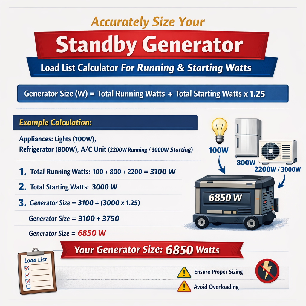
Standby Generator Sizing Calculator for Total Running and Starting Watts
Background and objectives for load list calculators
Standby generator selection depends on distinguishing continuous running watts from transient starting watts. A correct load list calculator will quantify each connected load's steady-state power demand and the additional transient current or power that occurs at motor start or compressor inrush. The objective is to size a generator to handle the expected steady-state load plus the starting surges without unacceptable voltage sag or nuisance load shedding.
This article provides an engineering-grade methodology for assembling an accurate load list, applying motor starting multipliers, using diversity and demand factors, converting watts to kVA, and selecting generator ratings.
Key concepts and definitions
- Running Watts (steady-state watts): continuous power a device consumes during normal operation.
- Starting Watts (surge or inrush watts): short-duration power or current required at motor or compressor start.
- Locked-Rotor Current (LRA): maximum starting current of an electric motor when rotor is stationary.
- Power Factor (PF): ratio of real power (kW) to apparent power (kVA); typically 0.8 for many generators under mixed loads.
- Service Factor (SF): manufacturers' allowed overload capability for continuous operation, used separately from starting capability.
- Diversity Factor: empirical reduction reflecting the probability that not all loads run simultaneously.
- kW and kVA: kW = real power (Watts/1000); kVA = apparent power = kW / PF.
Required inputs for an accurate load list calculator
- Detailed inventory of equipment: type, voltage, phase, rated horsepower (HP) for motors, and running watts.
- Starting characteristics: manufacturer locked-rotor current or recommended starting multiplier if LRA is unavailable.
- Operating profile: which loads are continuous, intermittent, or likely to start simultaneously.
- System constraints: acceptable voltage dip magnitude and duration, generator transfer switch behavior, and priorities for load shedding.
- Power factor assumptions for conversion to kVA for generator sizing.
Formulas and calculation workflow
Below are the essential formulas using only HTML-friendly notation. Each formula is followed by variable explanations and typical values used in calculators.
Convert running watts to kilowatts:
- RunningWatts: continuous device power in watts. Typical values: refrigerator 700 W running, air conditioner 3500 W running.
- kW_running: result in kilowatts.
Calculate starting watts using a starting multiplier:
- StartingMultiplier: dimensionless factor representing inrush (typical ranges: 3 to 8). See motor tables below.
- StartingWatts: transient surge power in watts for the duration of start.
Convert kW to kVA for generator sizing:
- PowerFactor: assumed generator/load PF. Common engineering assumption: 0.8 (80%) for mixed loads unless specified.
- kVA: apparent power rating required from the generator.
Aggregate steady-state and starting needs for simultaneous starts:
- Peak additional kW_for_simultaneous_starts: sum of incremental starting kW for those loads expected to start concurrently.
When multiple motors may start in sequence, estimate voltage dip tolerance and use motor reacceleration intervals or reduced-voltage starters. If acceptable, treat starts as sequential rather than simultaneous in the calculator.
Typical running watt values and starting multipliers
The following tables present common devices, their approximate running watts, and typical starting multipliers used in generator sizing calculators. Values are engineering approximations; always verify with manufacturer data when available.
| Device | Typical Running Watts | Starting Multiplier (typical) | Typical Starting Watts Range | Notes / References |
|---|---|---|---|---|
| Refrigerator (residential) | 300–900 W | 3–6 | 900–5400 W | Compressor motor; start time usually 0.5–2 s |
| Air Conditioner (central, 3-ton) | 3000–4200 W | 3–6 | 9000–25200 W | Consult AHRI or manufacturer's locked-rotor data |
| Well Pump (submersible, 1 HP) | 750–1200 W | 4–6 | 3000–7200 W | High starting torque; check LRA |
| Electric Water Heater (resistive) | 3000–4500 W | 1 (resistive) | 3000–4500 W | No motor start; continuous element |
| Lighting (LED, house) | 5–20 W per fixture | 1 | Equal to running watts | Negligible start surge |
| Single-phase motor (small) | Depends on HP | 3–7 | 3×–7× running | PSC, capacitor-start vary; consult NEMA MG1 |
| Three-phase motor (industrial) | Depends on HP | 4–8 (locked rotor) | 4×–8× running | Older motors higher LRA; VFDs and soft starters reduce inrush |
Motor starting guidance and standards
Motor locked-rotor current and starting torque characteristics are specified in standards and manufacturer nameplates. Key authoritative standards include:
- NEMA MG1 — Motors and Generators: provides locked-rotor current classes and typical starting data (nema.org).
- IEEE Std 141 (Red Book) — recommended practice for electrical power distribution for industrial plants.
- NFPA 110 — Standard for Emergency and Standby Power Systems: design, installation, testing for standby generators (nfpa.org).
Applying diversity and demand factors
Not every load is operating at rated capacity at the same time. Use diversity and demand factors to avoid gross oversizing while ensuring reliability.
- Diversity factors are empirically derived per facility type (residential, commercial, industrial).
- Example typical diversity: residential lighting and outlets may use 70–90% of nameplate; HVAC may require full capacity during peak conditions.
- When in doubt for emergency systems, design for worst-case simultaneous starts or implement staged starting/load shedding.
Step-by-step calculator workflow
- Inventory all loads: list name, running watts, voltage, phase, HP for motors, and whether they are essential loads.
- For each motor or compressor, determine StartingMultiplier from nameplate LRA or table—if nameplate LRA exists, convert current to watts: StartingWatts = Voltage × LRA × √3 (for three-phase) or Voltage × LRA for single-phase, then convert to watts.
- Decide simultaneous start groups: which devices will likely start at the same instant. Apply starting multipliers only for those simultaneous starts.
- Sum all running watts. Add incremental starting watts for simultaneous starts to compute peak watts.
- Convert peak kW to kVA using assumed PowerFactor: kVA = kW_peak / PF.
- Select generator with kVA rating greater than kVA required and with adequate transient capability (inrush handling) and engine torque reserve.
- Validate voltage dip performance: ensure generator can support the transient without dropping voltage below acceptable limits (typically ±10% or as system tolerance allows).
Conversion examples and calculations
Formulas revisited for both single-phase and three-phase motors. Use these conversions inside the calculator.
Single-phase starting watts from LRA:
- Voltage: supply voltage in volts (e.g., 120 V or 240 V).
- LRA: locked-rotor amperes from the motor nameplate.
Three-phase starting watts from LRA:
- Voltage: line-to-line voltage (e.g., 208 V, 480 V).
- √3 ~ 1.732.
Note: These formulas give apparent VA during start. To convert to real power (Watts), multiply by expected starting power factor if known, or approximate starting PF (often 0.3–0.6 during locked rotor). Many calculators conservatively use RunningWatts × StartingMultiplier instead.
Extensive tables: horsepower to running watts and starting multipliers
For motor-based loads, convert HP to running watts, then apply starting multiplier. Table below helps calculators and engineers.
| Motor HP | Typical Running kW (approx.) | Typical Running W | Starting Multiplier (Locked Rotor) | Typical Starting W Range |
|---|---|---|---|---|
| 0.25 HP | 0.186 kW | 186 W | 3–6 | 558–1116 W |
| 0.5 HP | 0.373 kW | 373 W | 3–6 | 1119–2238 W |
| 1 HP | 0.746 kW | 746 W | 4–6 | 2984–4476 W |
| 2 HP | 1.492 kW | 1492 W | 4–6 | 5968–8952 W |
| 5 HP | 3.73 kW | 3730 W | 4–7 | 14920–26110 W |
| 10 HP | 7.46 kW | 7460 W | 4–8 | 29840–59680 W |
| 25 HP | 18.65 kW | 18650 W | 5–8 | 93250–149200 W |
Real-world example 1 — Residential critical loads with central AC and well pump
Scenario: A 3-bedroom house requires a standby generator to feed essential circuits: central air (3-ton single-phase), refrigerator, well pump (1 HP), lighting and outlets, and an electric water heater is non-essential (excluded). The transfer switch connects only selected essential loads.
Inventory and manufacturer running watts (approximate):
- Central AC (3-ton): RunningWatts = 3600 W
- Refrigerator: RunningWatts = 700 W
- Well pump (1 HP): RunningWatts = 900 W
- Lighting and outlets (selected essential): RunningWatts = 800 W
- Small loads (router/controls): RunningWatts = 200 W
Step 1 — Sum running watts:
Step 2 — Determine starting multipliers for likely simultaneous starts. Assume central AC and refrigerator may start concurrently; well pump may start independently. Use multipliers:
- Central AC StartingMultiplier = 5 (manufacturer recommends 4–6; choose conservative 5)
- Refrigerator StartingMultiplier = 4
- Well pump StartingMultiplier = 5
Calculate starting watts:
If AC and refrigerator start simultaneously, peak incremental start above running is:
Assume well pump starts separately; if worst-case it also starts simultaneously, include it too:
Step 3 — Peak watts including running:
Step 5 — Select generator size. Choose a commercially available standby generator ≥ 30 kVA to provide margin for transient performance and inefficiencies. If well pump start must be included simultaneously, kVA_requirement:
Decision: If the transfer switch or control strategy prevents simultaneous pump and AC starts, a 30 kVA generator is adequate. For worst-case simultaneous starting including well pump, choose a 35 kVA generator and evaluate reduced-voltage starting or staged start to reduce required kVA.
Real-world example 2 — Small commercial site with three-phase motors and lighting
Scenario: Small commercial facility with the following essential loads connected to the standby system: two three-phase fans (5 HP each), one 10 HP refrigeration motor, lighting and outlets, and HVAC unit (single 7.5 HP three-phase compressor). All three-phase motors run at 480 V, 3-phase.
- 5 HP fan running W ≈ 3730 W (per HP table) each; two fans = 7460 W.
- 10 HP refrigeration motor running W ≈ 7460 W.
- 7.5 HP AC running W ≈ 5595 W.
- Lighting and small loads running W = 2000 W.
Total running watts:
Starting multipliers (conservative):
- 5 HP motors: StartingMultiplier = 6
- 10 HP motor: StartingMultiplier = 6
- 7.5 HP motor: StartingMultiplier = 6
Starting watts per motor:
If all motors start simultaneously (worst-case): incremental start above running:
Compute for each:
- Two 5HP fans: incremental each = 22380 - 3730 = 18650; two fans incremental = 37300 W
- 10HP incremental = 44760 - 7460 = 37300 W
- 7.5HP incremental = 33570 - 5595 = 27975 W
Sum incremental = 37300 + 37300 + 27975 = 102,? Calculate: 37300 + 37300 = 74600; 74600 + 27975 = 102575 W
Interpretation: A generator on the order of 160–200 kVA would be required to support simultaneous starting of all motors using direct-on-line starting. In commercial practice, staged start, soft starters, or VFDs reduce starting current dramatically. If soft starters reduce starting multiplier to 2.0 for larger motors, recalculate:
- 5HP start = 3730 × 3 = 11190 → incremental per fan = 7460? Wait compute incremental: 11190 - 3730 = 7460 per fan → two fans incremental = 14920 W
- 10HP start = 7460 × 2 = 14920 → incremental = 7460 W
- 7.5HP start = 5595 × 2.5 = 13987.5 → incremental = 8392.5 W
Conclusion for Example 2: Using soft starters or VFDs can reduce generator size requirement from roughly 160–200 kVA down to 75 kVA, demonstrating the value of reduced-voltage starting when generator sizing is constrained.
Practical considerations and control strategies
- Load shedding and priority switching: Use transfer switch logic to prevent simultaneous starts of high-inrush loads (staggers start times by seconds).
- Soft starters / VFDs: Implement for large motors to reduce inrush and enable smaller generator sizing and reduced mechanical stress.
- Ambient conditions: Generator rating and available power are affected by altitude and ambient temperature—apply altitude and temperature derating per manufacturer data.
- Generator transient capability: Engine torque and alternator short-term overload capacity matter; verify manufacturers' “motor starting capability” curves.
- Fuel system sizing: Run-time and fuel supply sizing must align with anticipated generator loading and runtime between refueling.
- Maintenance and periodic testing: NFPA 110 requires testing under load; simulated starting events should be part of commissioning.
Validation and voltage dip assessment
Transient voltage dip analysis helps ensure sensitive loads remain within acceptable voltage tolerance during motor starts. Use one of these approaches:
- Manufacturer motor data and alternator impedance curves for precise point-by-point simulation.
- Approximate method: estimate voltage dip % = (StartingCurrent × MotorImpedanceContribution) ÷ GeneratorNoLoadVoltage, or use starting power ratio method comparing starting VA to generator kVA.
Simple screening criterion often used: keep starting VA for simultaneous motors less than 300–400% of generator kVA per phase for acceptable voltage dips; for sensitive electronics, keep dips minimal and consider UPS or static transfer switches.
Regulatory and normative references
Key authoritative standards and resources you should consult while developing or validating a load list calculator and generator specification:
- NFPA 110 — Standard for Emergency and Standby Power Systems. https://www.nfpa.org/
- NFPA 70 (NEC) — National Electrical Code: Articles on standby and emergency systems, transfer equipment, and overcurrent protection. https://www.nfpa.org/
- NEMA MG1 — Motors and Generators: performance and starting data; see NEMA website. https://www.nema.org/
- IEEE Std 1547 — Interconnection and interoperability of distributed energy resources with the electric power systems. https://standards.ieee.org/
- Generator manufacturers’ technical guides — e.g., Cummins, Caterpillar, Kohler provide motor starting guides and generator sizing tools. Example: https://www.cummins.com/ or https://www.cat.com/
- ASHRAE and AHRI — for HVAC equipment performance and starting data (ahrinet.org).
Calculator implementation tips for engineers and developers
- Require users to input nameplate LRA whenever available. LRA produces more accurate starting VA than generic multipliers.
- Provide default multipliers by device and motor type but allow overrides.
- Allow grouping by simultaneous start groups and provide presets for residential, commercial, and industrial scenarios.
- Include power factor selection per load category and a global PF assumption for kVA conversion; allow dynamic PF calculation for motor starting if starting power factor is supplied.
- Show intermediate results: running kW, starting kW incremental, peak kW, kVA required, and recommended generator sizes with margin.
- Incorporate derating for altitude and ambient temperature per generator manufacturer curves.
- Implement warning flags when inrush requirements exceed typical generator short-circuit capability and recommend staged starts or soft starters.
Summary of recommended engineering practice
- Always prioritize obtaining manufacturer starting data (LRA and starting PF) before using conservative multipliers.
- Design transfer switch and controls to prevent unnecessary simultaneous starts when possible.
- Consider reduced-voltage starting or VFDs for large motors to reduce generator size and mechanical stress.
- Use NFPA 110 and NEC guidance for sizing emergency and standby installations and for commissioning/testing requirements.
- Include testing under simulated starting conditions during commissioning to validate real-world performance.
Additional resources and further reading
- NFPA 110: https://www.nfpa.org/ — standard for emergency and standby power systems.
- NFPA 70 (NEC): https://www.nfpa.org/ — code requirements for standby systems and transfer equipment.
- NEMA MG1 motor standards and starting classifications: https://www.nema.org/
- IEEE Guide for Electric Power Distribution: https://standards.ieee.org/
- Generator manufacturers’ motor starting guides (examples): Cummins, Caterpillar, Kohler (see their technical application notes).
Final engineering checklist before generator procurement
- Confirm final essential loads and obtain up-to-date manufacturer nameplate data for motors and compressors.
- Model simultaneous start scenarios and assess staged starting strategies.
- Compute kVA requirements using realistic power factor and include safety margin (typically 10–20%).
- Select generator based on kVA and transient capability; validate with manufacturer motor-start capability curves.
- Specify controls for load shedding, reduced-voltage starting, and protective interlocks.
- Plan for commissioning tests under full simulated load and record voltage dip, frequency stability, and transfer performance per NFPA 110.
Accurate generator sizing requires combining nameplate data, realistic simultaneous start modelling, diversity/demand factors, and a conservative conversion to kVA considering power factor. Using the explicated formulas, tables, and examples above, engineers and installers can construct a reliable standby generator load list calculator that balances resilience, cost, and equipment protection.