This article presents a practical SCR at PCC calculator methodology for power system engineers globally.
It explains comparing fault current versus load current with IEEE 519 guidance, typical input parameters.
Short-Circuit Ratio (Isc/IL) at PCC – Compare Fault Current vs Load Current per IEEE 519
Context and scope for SCR at PCC calculations
This document sets a rigorous technical framework for computing Short-Circuit Ratio (SCR) at the Point of Common Coupling (PCC), comparing available fault current versus actual load current and interpreting results against IEEE 519 guidance. It is aimed at protection, planning and power quality engineers who need a repeatable calculation workflow, formula set, typical values, and worked examples suitable for tool implementation or manual checks.
Key concepts and definitions
Before presenting the calculation method, clarify the main electrical quantities and their relevance in planning and harmonic assessment:
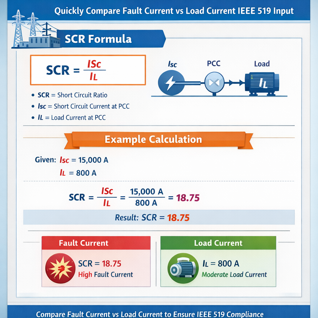
- I_sc (or I_fault): Available bolted three-phase short-circuit current at PCC (RMS, amperes).
- I_load (or I_L): Maximum demand (fundamental frequency) RMS load current at PCC (amperes).
- S_sc: Short-circuit apparent power at PCC (MVA or kVA).
- S_load: Apparent power of the connected load or generating unit (MVA or kVA).
- SCR: Short Circuit Ratio, a non-dimensional metric expressing network strength at PCC.
- PCC: Point of Common Coupling — physical point where the customer or generator connects to the distribution/transmission network.
Why SCR at PCC matters
- Determines system stiffness: higher SCR indicates a stronger, less sensitive system to disturbances and harmonics.
- Influences inverter/converter behaviour, voltage support, and stability; weak PCCs (low SCR) may require additional control or grid-forming capabilities.
- Used in IEEE 519 harmonic assessments where the ratio of short-circuit current to load/current injection affects allowable harmonic injection and mitigation strategies.
- Direct input for protection design and relay setting coordination: fault current magnitude defines device interrupting ratings and settings.
Primary formulas and their explanations
All formulas are expressed using plain HTML-text notation. Each formula is followed by detailed variable definitions and typical values.
Fundamental SCR (current basis):
- I_sc — Available three-phase short-circuit current at PCC (A). Typical values: 500 A (weak rural) to 50,000 A (strong transmission bus).
- I_load — Maximum demand fundamental RMS current at PCC (A). Typical values: tens to thousands of amperes depending on connected load or generator rating.
Alternative SCR (MVA basis):
- S_sc = 1.732 × V_ll(kV) × I_sc(kA) (MVA). Note: use consistent units—if V in kV and I in kA, result is MVA. Typical S_sc: from a few MVA (weak feeders) to several thousand MVA (transmission).
- S_load — Apparent power of the connected plant (MVA). For loads use maximum demand or installed capacity for generation connections.
Conversion of fault current to short-circuit MVA (explicit):
- V_ll — Line-to-line RMS voltage in kV at PCC. Typical values: 0.4 kV (low-voltage LV), 11 kV/13.8 kV (distribution), 33 kV, 69 kV, 132 kV.
- I_sc(kA) — Short-circuit current expressed in kiloamperes (kA).
Load current from power:
- P — Active power in kW (use maximum demand or generator active rating).
- pf — Power factor (lagging for inductive loads). Typical pf: 0.85–0.95 industrial; 1.0 for inverter-based generation considered at unity for initial sizing.
Measurement and calculation workflow at PCC
- Collect network data:
- Nominal voltage (V_ll) at PCC.
- Available three-phase short-circuit current I_sc at PCC (from system studies or substation relay reports).
- Maximum demand load or generator apparent power S_load or active power P and pf.
- Frequency and configuration (three-phase balanced assumed for SCR calculations).
- Compute S_sc if only I_sc is available using S_sc = 1.732 × V_ll × I_sc (consistent units).
- Compute I_load from P and V (or directly use measured I_load).
- Compute SCR = I_sc / I_load (or S_sc / S_load).
- Interpret SCR using published guidance and standards; apply mitigation or design changes if SCR is below thresholds relevant to equipment behaviour or harmonic acceptance.
Typical values and interpretation table
| Voltage Level (kV) | Typical Available I_sc (kA) | S_sc (MVA) at Typical I_sc | Example Load S_load (MVA) | Example SCR (S_sc/S_load) | Interpretation |
|---|---|---|---|---|---|
| 0.4 (LV) | 0.5 | 0.346 | 0.1 | 3.46 | Weak distribution feeder, sensitive to distortion |
| 6.6 | 5 | 57.0 | 5 | 11.4 | Moderate strength, acceptable for most inverters |
| 11 | 10 | 190.5 | 10 | 19.05 | Strong distribution/subtransmission |
| 13.8 | 15 | 358.5 | 20 | 17.93 | Strong; robust fault capacity |
| 33 | 20 | 1141.5 | 50 | 22.83 | Transmission-level strength |
| 132 | 40 | 9154.0 | 500 | 18.31 | Very strong grid |
SCR interpretation bands and typical mitigation
| SCR range (approx.) | System character | Expected impact on converters/inverters | Typical mitigation or design response |
|---|---|---|---|
| < 3 | Very weak | Large voltage excursions; potential unstable grid-following inverters | Grid-forming controls, dynamic reactive support, series reactors, upgrade substation strength |
| 3 – 6 | Weak | Possible ride-through issues; harmonic amplification | Active damping, harmonic filters, tuning of PLL and control loops |
| 6 – 10 | Moderate | Most modern inverters function, but check harmonic limits | Standard testing and conservative control gains; possible small filters |
| > 10 | Strong | Stable; low interaction risk | Normal commission and standard protection settings |
Applying IEEE 519 considerations
IEEE Std 519 addresses limits on voltage distortion and provides methodology references for assessing harmonic interactions. A key parameter used in harmonic assessment and equipment acceptance is the ratio of available short-circuit current at PCC to the maximum load or converter injected current (I_sc / I_L). A larger I_sc / I_L implies the network is stiffer and will attenuate injected harmonic currents more effectively; smaller ratios mean network impedance is higher relative to the injected harmonic sources and require stricter harmonic control.
- Use measured or studied I_sc at the PCC from a power system fault study.
- Use maximum continuous current for I_L (from customer maximum demand or rated inverter current) in the denominator.
- Check IEEE 519 recommended harmonic current injection limits using the ratio to determine if additional filtering or active control is required.
Reference authoritative items for normative compliance:
- IEEE Std 519-2014 — Recommended Practice and Requirements for Harmonic Control in Electric Power Systems (https://standards.ieee.org/standard/519-2014.html).
- IEC 60909 — Short-circuit current calculation rules (https://www.iec.ch/).
- IEEE Std 399 (Brown Book) — Power System Analysis for planning and equipment sizing (https://standards.ieee.org/standard/399/).
Design and protection implications of SCR values
SCR at the PCC impacts multiple design domains:
- Protection device selection: higher I_sc dictates interrupting capacity of circuit breakers and fuses; lower I_sc may prolong fault clearing and reduce relay sensitivity.
- Power quality and harmonic distortion: low SCR networks are more susceptible to harmonic voltage distortion for the same harmonic current injection.
- Converter/inverter control tuning: PLL and control gains must be adjusted for lower SCR to avoid instability and current distortion.
- Generator-inertia and frequency response: local inertia interactions are typically more critical on weak systems.
Practical calculator algorithm (step-by-step)
- Input data:
- Nominal line-to-line voltage V_ll (kV).
- Available three-phase short-circuit current I_sc (A) or S_sc (MVA).
- Load or generator rating P (kW) and pf, or S_load (kVA/MVA) directly.
- Prefer measured I_load if available; otherwise calculate from P and pf.
- Preprocessing:
- Convert I_sc to kA if using S_sc formula: I_sc(kA) = I_sc(A) / 1000.
- Compute S_sc(MVA) = 1.732 × V_ll(kV) × I_sc(kA) if S_sc not provided.
- Compute S_load(MVA) = P(kW)/1000 / pf if only active power provided (approximate for small phase angles).
- Compute both SCR metrics:
- SCR_current = I_sc / I_load.
- SCR_MVA = S_sc / S_load.
- Compare SCR against thresholds and IEEE 519 context; output warnings and mitigation suggestions if SCR < target range.
Worked example 1 — Distribution feeder where I_sc known
Scenario: A 13.8 kV distribution feeder supplies an industrial site. The available three-phase bolted fault current at the PCC is measured as I_sc = 12.5 kA. The customer's maximum demand is P = 12 MW at pf = 0.92. Determine SCR (current and MVA basis) and assess system strength.
Calculation steps
- Step 1 — Convert inputs and compute I_load:I_load(A) = P(kW) / (1.732 × V_ll(kV) × pf) × 1000
First convert P to kW: 12 MW = 12,000 kW.
I_load = 12,000 / (1.732 × 13.8 × 0.92) = 12,000 / (22.01184) = 545.4 A (approx).
- Step 2 — Compute SCR (current basis):SCR = I_sc / I_load = 12,500 A / 545.4 A = 22.92
Interpretation: SCR ≈ 23 indicates a very strong connection at PCC; harmonic injection attenuation will be high.
- Step 3 — Compute S_sc to verify MVA basis:I_sc in kA = 12.5 kAS_sc = 1.732 × V_ll(kV) × I_sc(kA) = 1.732 × 13.8 × 12.5 = 298.9 MVAS_load approximate (MVA) = P(kW)/1000 / pf = 12,000/1000 / 0.92 = 13.04 MVASCR_MVA = S_sc / S_load = 298.9 / 13.04 = 22.9 (consistent with current-based SCR)
- Step 4 — Conclusion and recommendation:
With SCR ≈ 23, standard converter designs and harmonic compliance per IEEE 519 are easily achievable without additional filtering. Protection devices must be rated for interrupting currents beyond 12.5 kA.
Worked example 2 — Weak rural connection with inverter farm
Scenario: A 33 kV rural substation has measured three-phase short-circuit current I_sc = 2.4 kA. A 20 MVA inverter-based generator plant proposes interconnection. Evaluate SCR and implications for inverter control and harmonic limits.
Calculation steps
- Step 1 — Compute S_sc from I_sc:I_sc(kA) = 2.4 kAS_sc(MVA) = 1.732 × V_ll(kV) × I_sc(kA) = 1.732 × 33 × 2.4 = 137.1 MVA
- Step 2 — Use generator rating as S_load (cause plant is inverter-based with rated MVA = 20 MVA):S_load = 20 MVASCR_MVA = S_sc / S_load = 137.1 / 20 = 6.855
- Step 3 — Compute current-based SCR for a cross-check (optional):
Assume inverter rated apparent current I_inv = S_load / (1.732 × V_ll) = 20,000 kVA / (1.732 × 33 kV) = 350.0 A
I_sc = 2400 A, so SCR_current = I_sc / I_inv = 2400 / 350 = 6.86 (consistent) - Step 4 — Interpretation:
SCR ≈ 6.9 falls in the "moderate" band (3–10). The site is not very weak, but converter controls should be tuned and harmonic emission assessed carefully per IEEE 519. Active damping or small filters may be necessary to meet harmonic current injection limits and to ensure stable PLL behaviour during disturbances.
- Step 5 — Recommended actions:
- Perform detailed harmonic emission study using the measured I_sc and worst-case I_L per IEEE 519 methodology.
- Tune inverter PLL and droop/reactive control for low-SCR operation; include low-voltage ride-through (LVRT) testing.
- Consider adding static synchronous compensator (STATCOM) or small passive filters if harmonic limits cannot be met.
Additional worked example — fault current vs load current comparison for protection
Scenario: 11 kV feeder with protective device selection. Available short-circuit current I_sc = 8 kA. Customer maximum demand P = 3.5 MW at pf = 0.9. Determine I_load, SCR, and check breaker interrupting requirement.
Calculation steps
- I_load = P(kW) / (1.732 × V_ll × pf) × 1000 = 3,500 / (1.732 × 11 × 0.9) × 1000Compute denominator: 1.732 × 11 × 0.9 = 17.136I_load = 3,500 / 17.136 = 204.3 A
- SCR = I_sc / I_load = 8,000 / 204.3 = 39.17 (very strong)
- Breaker interrupting rating must exceed the maximum possible symmetrical fault current plus safety margin; specify CB rating ≥ 1.1 × 8 kA = 8.8 kA (practically choose 10 kA or 25 kA standard rating depending on procurement and future-proofing).
- Protection coordination: high fault current will allow fast clearing but select relays and CTs with adequate accuracy at both fault and load currents.
Common pitfalls and recommended checks
- Unit consistency: ensure voltage in kV, current in kA or A consistently across formulas; S_sc formula expects kV and kA to yield MVA directly.
- Use maximum demand/current (not average) for I_load in SCR computations when assessing harmonic injections or stressing conditions.
- When I_sc is not directly measured, derive it from system model or vendor-provided short-circuit MVA at PCC; verify model assumptions (transformer impedances, fault contributions, breaker status).
- Remember that GIC and DC offsets are not included in symmetrical RMS-based SCR; some converters respond to sub-cycle dynamics—include time-domain studies for control design when SCR is low.
- IEEE 519 harmonic assessment requires comprehensive studies beyond SCR alone; use SCR as a network-strength indicator feeding into full harmonic impedance calculations.
How to present input fields for a free SCR at PCC calculator (UI/UX recommendations)
- Essential inputs:
- Nominal line-to-line voltage (kV)
- Available three-phase short-circuit current at PCC (A or kA) OR S_sc (MVA)
- Maximum demand P (kW or MW) and power factor OR S_load (MVA)
- Optional: measured I_load (A) override, transformer impedance data, multiple contingencies selection
- Outputs should include:
- SCR (current basis) and SCR (MVA basis)
- S_sc and S_load values with units
- Interpretive band (weak/moderate/strong) and recommended actions
- Printable report with input snapshot and step-by-step calculations
- Validation checks:
- Flag inconsistent units
- Require either I_sc or S_sc (not both blank)
- Warn for unrealistic SCR (>100) or extremely low (<0.5)
Regulatory and normative references
When designing interconnections and validating harmonic performance, reference the following authoritative documents and resources:
- IEEE Std 519-2014, "IEEE Recommended Practice and Requirements for Harmonic Control in Electric Power Systems" — key document for harmonic limits and assessment methodology. https://standards.ieee.org/standard/519-2014.html
- IEC 60909, "Short-circuit currents in three-phase AC systems" — recommended for consistent short-circuit calculation methods. https://www.iec.ch/
- IEEE Std 399 (The Brown Book) — power system analysis and planning guidance. https://standards.ieee.org/standard/399-1997.html
- NERC and national grid codes — check local interconnection requirements and protection settings (e.g., NERC planning standards at https://www.nerc.com/).
- Manufacturer and inverter technical application notes on minimum PCC strength and required SCR for grid-following/grid-forming operation (consult vendor documentation).
Summary of best practices
- Always use measured or study-derived I_sc at PCC whenever possible; avoid rule-of-thumb approximations for critical projects.
- Compute SCR using both current and MVA bases to cross-check results and ensure unit consistency.
- Use SCR values as a first-order indicator for harmonic and stability risk; follow IEEE 519 and IEC 60909 for detailed compliance and calculation methodology.
- If SCR is below the recommended band for your equipment, plan for mitigation (filtering, active control, reactive support) before commissioning.
- Document all assumptions and produce a traceable calculation report for regulatory or interconnection review.
Further reading and authoritative links
- IEEE Std 519-2014 — Recommended Practice and Requirements for Harmonic Control in Electric Power Systems: https://standards.ieee.org/standard/519-2014.html
- IEC 60909 — Short-circuit current calculations in three-phase AC systems: https://www.iec.ch/
- IEEE PES resources and tutorials on short-circuit analysis: https://resourcecenter.ieee-pes.org/
- NERC reliability standards and planning guidelines: https://www.nerc.com/
- NREL technical reports and inverter grid interconnection discussions (useful for SCR and inverter interactions): https://www.nrel.gov/
By following the formulas and workflows above, and using the example calculations for verification, you can implement a reliable free SCR-at-PCC calculator or perform manual checks to compare fault current versus load current and meet IEEE 519 input requirements for harmonic assessments.