Proper electrical service sizing prevents nuisance tripping, inefficiency, and unnecessary installation, maintenance, and operating costs. Accurate calculated loads per code and utility data yield safe, economical, and right-sized electrical service selections.
Avoid Oversizing: Select US Electrical Service Size from Calculated Load
Principles of Accurate Service Sizing and Why Oversizing Is Harmful
Oversizing a service can increase capital expenses, utility fees, equipment costs, and reduce system efficiency.
Correct service sizing balances safety margins, code requirements, diversity, and realistic load growth expectations.
Technical risks of oversizing
- Unnecessary transformer and meter upgrades increase initial capital and sometimes ongoing demand charges.
- Protective device coordination becomes more complex; oversized upstream devices can delay fault isolation.
- Higher cost conductors and switchgear, and physical space and installation complexity increase.
- Energy efficiency: oversized service often leads to oversized downstream equipment with reduced partial-load efficiency.
Regulatory and contractual drivers
- National Electrical Code (NFPA 70) mandates methods for calculated load and conductor sizing.
- Local utility service rules may impose minimum service sizes, transformer sizing rules, and metering requirements.
- Engineering practice requires applying demand factors, diversity, and continuous-load multipliers to comply with NEC.
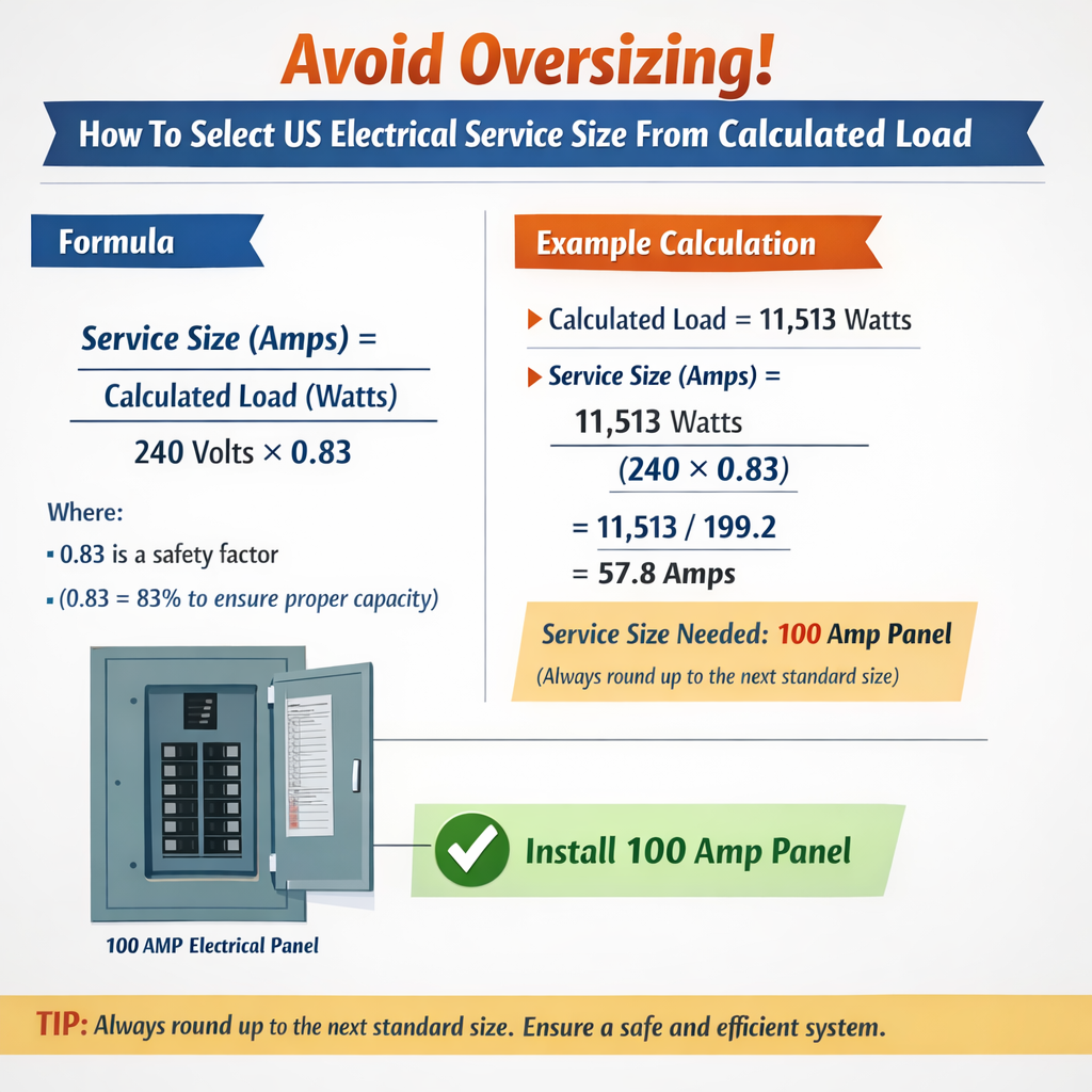
Core Formulas Used in Service Selection
Below are the fundamental calculation formulas with explanations and typical values for the variables.
Conversion to current for single-phase systems:
Variables:
- I — Current in amperes (A)
- P — Real power or apparent power in watts or volt-amperes (W or VA)
- V — Line-to-line or line-to-neutral voltage as appropriate (V); for residential single-phase typically 120/240 V
Conversion to current for three-phase systems:
Variables:
- I — Line current (A)
- P — Total apparent power in VA
- √3 — Square root of three ≈ 1.732
- V — Line-to-line voltage (V), e.g., 480 V for many commercial systems
- pf — Power factor (unitless), typical values 0.8–1.0; motors often 0.85–0.95 unloaded
Service sizing decision rule (simplified):
Variables:
- continuous current — load current that operates for 3 hours or more (A)
- non-continuous peak — intermittent loads (A)
- Typical rounding — standard service sizes: 100 A, 150 A, 200 A, 400 A, 800 A, etc.
Step-by-Step Workflow Using a Calculated Load Calculator (11513)
This workflow converts connected loads into a code-compliant recommended service size while avoiding oversizing.
- Collect nameplate data for every load: lighting, receptacles, HVAC, water heaters, ranges, dryers, fixed equipment, motors, and special loads.
- Classify loads as continuous (≥3 hours), non-continuous, motor loads, or HVAC peak loads.
- Apply code-prescribed demand factors for specific categories (e.g., small-appliance and laundry circuits, ranges, water heaters) and building types. Use conservative defaults when unknown.
- Sum adjusted loads to obtain total VA. Apply 125% multiplier to continuous loads when determining conductor ampacity and equipment ratings, per standard practice.
- Convert VA to amperes for the system voltage and phase. For three-phase include √3 and pf as needed.
- Round up to the nearest commercially available service size, but evaluate if a smaller sized service can be justified by further documented demand diversity, utility rules, or load-management strategies.
- Confirm coordination with utility minimums, transformer sizing, inverter or generator interface, and service equipment ratings.
Tables of Common Values and Demand Factors
| Load Category | Typical Nameplate VA per Unit | Common Quantity Examples | Typical Demand Factor or Comment |
|---|---|---|---|
| General Lighting | 1.0 W/ft² to 3.0 W/ft² (residential to commercial) | Single-family 1,800 ft² → 1,800–5,400 W | Use code-specified VA/ft²; diversity often applied for dwelling |
| Small Appliance Circuits | 1,500 VA per circuit | Typical 2 circuits in single-family kitchens | Code applies demand factors (see NEC) for multiple circuits |
| Range (electric) | 12,000–12,500 VA (residential) up to 16,000+ VA (commercial) | One per dwelling unit | Apply range demand factor table when multiple |
| Clothes Dryer | 3,000–7,000 VA | Usually one per dwelling unit | Dryers often listed as non-continuous; apply code guidance |
| Water Heater (Electric) | 3,000–5,500 VA | One per dwelling | Consider diversity; may be considered continuous when on timer |
| HVAC (Air Conditioner) | 2,000–12,000 VA (residential split) up to 30,000+ VA (commercial) | 1–4 units typical | Motors have starting currents; include lock-rotor and service factor loads |
| Motors | Full-load amps per motor nameplate | Varies: fractional to hundreds of HP | Apply NEC motor branch-circuit sizing and 125% rules as required |
| Service Rating (A) | Typical Transformer kVA | Conductor Size Typical (Cu) | Common Application |
|---|---|---|---|
| 100 A | 25–37.5 kVA | 3/0 AWG aluminum or 4 AWG copper for 240 V residential | Small homes, light commercial |
| 150 A | 37.5–75 kVA | 3/0–2/0 Al or 2 AWG Cu | Larger dwellings, moderate commercial |
| 200 A | 75–150 kVA | 4/0 Al or 2/0 Cu | Most modern single-family service |
| 400 A | 225–500 kVA | 250–600 kcmil Al or 350–600 kcmil Cu | Large multi-family, small industrial |
| 800 A+ | 500 kVA+ | 600 kcmil and larger | Large industrial and heavy commercial |
Demand Factor and Diversity Considerations
Applying demand factors is essential to avoid oversizing while ensuring compliance.
- Appliances: Use code-issued demand factors for ranges, dryers, water heaters, and cooking equipment.
- Multiple dwelling units: Provide unit load method or per-unit demand application depending on occupancy.
- Motors: Do not apply diversity to required motors for life-safety or continuous industrial processes unless specified.
Continuous Load Rule
For loads expected to persist three hours or more, increase the continuous load by 25% when sizing conductors and overcurrent devices:
Typical example: HVAC compressor running steady for 3+ hours requires 125% for conductor ampacity check.
Example 1 — Residential Single-Family Dwelling Load Calculation (Detailed)
Scenario: 2,200 ft², 3-bedroom house with electric range, dishwasher, laundry, electric water heater, central AC.
Step A: Collect nameplate and standard VA values
- Lighting: 2,200 ft² × 3 W/ft² = 6,600 VA
- Small appliance circuits: 2 circuits × 1,500 VA = 3,000 VA
- Laundry circuit: 1,500 VA
- Range (electric): 12,500 VA (nameplate)
- Electric dryer: 5,000 VA
- Water heater (electric): 4,500 VA
- HVAC (split system): 4-ton unit ~ 36,000 BTU → approximate 9,000 VA (nameplate varies)
- Miscellaneous loads (chargers, entertainment, pump): estimate 2,000 VA
Step B: Apply applicable demand factors
- Lighting and general loads: use full VA unless local code specifies VA/ft² demand adjustments.
- Small appliance and laundry circuits: apply NEC small-appliance demand factor — for one dwelling we typically use 3,000 VA total (two circuits) as calculated.
- Range demand factor: for a single dwelling, full appliance load is commonly used (12,500 VA).
- Dryer and water heater: treated as separate loads — if both are not likely continuous concurrently, some diversity allowed by code; conservatively include full values for safety.
Step C: Sum loads to get total VA
Total connected VA = 6,600 + 3,000 + 1,500 + 12,500 + 5,000 + 4,500 + 9,000 + 2,000 = 44,100 VA
Step D: Convert to service current (single-phase 240 V)
Step E: Apply continuous-load multiplier where appropriate and select service size
Identify continuous components: HVAC might be continuous in extreme climates; water heater may be intermittent. For safety, assume HVAC continuous and apply 125%:
Adjusted contribution = HVAC current × 1.25.
Recalculate total current subtracting original HVAC current and adding adjusted HVAC current:
Step F: Round to standard service and verify
193.125 A requires at least a 200 A service. Select 200 A main breaker panel.
Conductor selection example (aluminum service conductors): 200 A typically uses 4/0 Al or 2/0 Cu depending on temperature and installation conditions; verify ampacity tables and adjustment factors.
Commentary and optimization
- Documented load management (e.g., load shedding of water heater during peaks) could justify a 150 A service if validated by calculated demand and utility acceptance.
- Do not oversize to 400 A without documented future loads or tenant demands; a 200 A service meets the calculated requirement and code.
Example 2 — Small Commercial Building Three-Phase Service Calculation (Detailed)
Scenario: 5,000 ft² small office with fluorescent lighting, computer loads, small kitchenette (range 12 kVA), a server room (dedicated 5 kVA), HVAC rooftop unit 20 kW (two units), and one 10 HP motor-driven rooftop exhaust fan.
Step A: Nameplate and estimated VA
- Lighting: 5,000 ft² × 2 W/ft² = 10,000 VA
- Receptacle/computers: estimate 3 VA/ft² → 15,000 VA
- Kitchen range: 12,000 VA
- Server room: 5,000 VA (continuous)
- HVAC: 20 kW × 2 units = 40,000 W → 40,000 VA (assume pf = 1 for simplification)
- 10 HP motor: 10 HP × 746 W/HP = 7,460 W → nameplate current and starting characteristics required; use full-load VA = 7,460 VA
- Miscellaneous: 2,000 VA
Step B: Apply demand factors and classification
- Server room and other continuous loads: treat as continuous and apply 125% for conductor sizing.
- Lighting and receptacles: diversity may be applied per commercial lighting and receptacle rules; use full values if conservative.
Step C: Total connected VA
Step D: Convert to line current (three-phase, 480 V)
Step E: Continuous-load adjustments
Server room is continuous (5,000 VA). HVAC may operate long periods seasonally—treat HVAC as continuous for sizing precaution:
Step F: Service sizing and roundup
137.28 A per phase suggests selecting a 150 A three-phase service at 480 V or a 160 A if custom. Standard commercial service panels commonly come in 150 A and 200 A ratings.
Selecting a 150 A service is acceptable if coordination, protective devices, and utility transformer availability are verified. In many utilities, 150 A three-phase is less common; often 200 A per phase or a kVA transformer sized at 125–150 kVA will be chosen. Verify with utility.
Motor starting considerations
- The 10 HP motor has high starting current; ensure service and feeder short-circuit capacity and motor starting methods (direct-on-line vs. soft starter) are considered.
- Coordinate inrush and consider load management delays if multiple motors start simultaneously.
Best Practices to Avoid Oversizing While Ensuring Safety
- Start with detailed load inventory and verified nameplate data; avoid rule-of-thumb assumptions when precision matters.
- Use published demand-factor tables from the code (NFPA 70 / NEC) and documented utility rules for multiple units and diversified loads.
- Consider demand-management strategies: time-of-use load shifting, load shedding, soft starters, and VFDs to reduce peak inrush.
- Document rationale for any allowance of diversity or reduction of conservative loads; acceptance by authority having jurisdiction (AHJ) and utility may be required.
- Plan for foreseeable growth but prefer modular expansion (e.g., service with space for future switchgear) rather than immediate oversizing.
- Perform harmonics and power quality analysis when non-linear loads are present; oversizing will not solve harmonic distortion issues.
Verification, Coordination, and Final Checks
- Verify conductor ampacity tables (ambient temperature correction and conduit fill adjustments).
- Confirm overcurrent protective devices meet NEC sizing and coordination rules. Verify 125% continuous load rule.
- Coordinate with the utility for transformer sizing, metering, primary-side fusing, and meter base ratings.
- Check mechanical clearances, switchgear dimensions, and access for the selected service size.
- Obtain AHJ approval where deviations from conservative sizing are proposed.
References, Code Citations, and External Resources
- NFPA 70, National Electrical Code — authoritative standard for electrical installations: https://www.nfpa.org/NEC
- IEEE Standards and recommended practices for power system design: https://standards.ieee.org
- Underwriters Laboratories (UL) standards and guidance for equipment ratings: https://www.ul.com
- U.S. Department of Energy — energy efficiency and load-management guidance: https://www.energy.gov
- NEMA — equipment ratings and enclosures: https://www.nema.org
- Local utility interconnection and service requirements — consult local utility websites and service guides (e.g., distribution or meter sizing documents).
Checklist for Using a Calculated Load Calculator (11513) Safely
- Input verified nameplate voltages, VA/kW values, and motor full-load amps rather than estimates wherever possible.
- Classify each load as continuous or non-continuous; mark life-safety circuits.
- Apply code-specified demand factors and multipliers; flag items that require AHJ interpretation.
- Include power factor for three-phase loads; do not assume unity for motors and non-linear loads.
- Evaluate motor starting methods, generator interaction, and UPS loads when present.
- Run sensitivity analysis: calculate with and without planned future loads and with various demand-factor scenarios to justify final service.
Final Recommendations for Engineers and Designers
- Design to code and documented load calculations; avoid arbitrary up-sizing without technical justification.
- Use modern calculators that support itemized loads, continuous load flags, and built-in demand tables to reduce human error.
- Coordinate early with the utility and AHJ to align expectations and avoid rework.
- When in doubt, choose strategies that reduce peak (load scheduling, VFDs, diversity) rather than simply increasing service amperage.
Key takeaways
- Oversizing increases cost and complexity; accurate calculated loads and demand factors produce safe, economical services.
- Use the 125% rule for continuous loads and apply code demand factors for appliances and receptacle circuits.
- Document assumptions and obtain approvals for any reductions from conservative approaches.
Further Reading and Tools
- NFPA 70 (NEC) handbook for commentary and application guidance: https://www.nfpa.org/NEC
- IEEE Power & Energy Society resources for system planning and motor starting: https://resourcecenter.ieee-pes.org/
- Utility interconnection guides — search your local utility site for distribution design and transformer application guidelines.
Accurate, documented, and code-compliant calculations produce right-sized services that save money, space, and operational costs while maintaining safety and reliability.