Accurate insulation level calculations ensure safety and compliance for high-voltage equipment in diverse systems worldwide.
An IEC-aligned calculator integrates impulse, switching and power-frequency withstand voltage assessments for engineering maintenance teams.
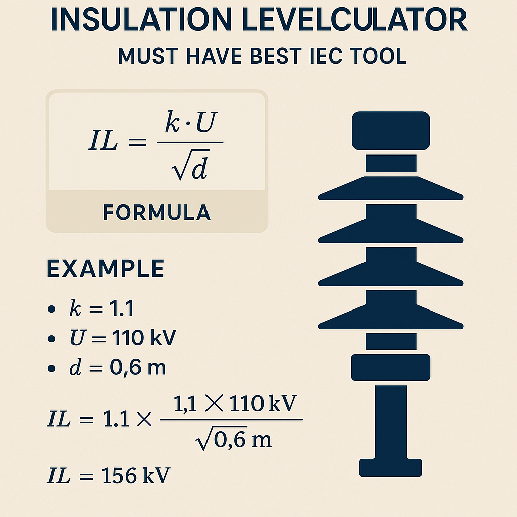
Insulation Level Calculator — IEC-oriented recommendation tool
Overview of an IEC-compliant Insulation Level Calculator
An Insulation Level Calculator designed for IEC compliance must embed standardized withstand criteria, statistical probabilistic methods, and automated conversion between different voltage representations. The tool must support impulse (1.2/50 µs), switching impulse (250/2500 µs), and power-frequency (50/60 Hz) withstand voltages, including conversion to peak, RMS, and crest values as required by IEC 60060 and IEC 60071 series.Key capabilities that make such a tool the "must-have" IEC instrument:- Selectable IEC normative tables for standard system voltages (e.g., 1 kV to 1200 kV).
- Computation of Basic Insulation Level (BIL), Highest Voltage for Equipment (Um), and coordination clearances.
- Monte Carlo or statistical margin analysis to translate test levels to onsite service risk (flashover probabilities).
- Support for impulse front and tail times, switching surge shapes, and combination wave statistics.
- Exportable reports with normative references and traceable calculation steps for audits.
Normative Basis and Regulatory References
An authoritative calculator references and implements clauses directly from relevant standards:- IEC 60060-1: High-voltage test techniques — Definitions and general test requirements — defines impulse wave shapes and measurement methods. (https://www.iec.ch)
- IEC 60060-2: High-voltage test techniques — Measuring systems — requirements for measuring instruments.
- IEC 60071-1 / 60071-2: Insulation co-ordination — principles and application guidelines for impulse, switching and power-frequency withstands. (https://www.iec.ch)
- IEEE Std C37.010 and IEEE C37.20 for equipment-specific dielectric requirements and clearances. (https://standards.ieee.org)
- CIGRÉ technical brochures for practical lightning and switching surge statistics on overhead lines and transformers. (https://www.cigre.org)
Technical Definitions and Conversion Conventions
Accurate calculations require consistent definitions:- Peak voltage (Vpk): maximum instantaneous value of a waveform.
- Root-mean-square (Vrms): effective heating value of a sinusoid; Vrms = Vpk ÷ √2 for pure sinusoids.
- Impulse standardized waveform 1.2/50 µs: crest time 1.2 µs, time to half-value 50 µs as defined in IEC 60060.
- Switching impulse waveform 250/2500 µs: used for system switching performance assessment.
- Basic Insulation Level (BIL): standardized impulse withstand value used historically for insulation coordination.
Core Formulas and Variable Explanations
Below are primary formulas the IEC-based calculator must implement. Each formula is written using HTML characters and plain text notation. Variable explanations and typical values follow.Conversion between RMS and Peak
Variables:
- V_peak: Peak (crest) voltage [kV]. Typical values: for 132 kV system, phase-to-earth V_peak ≈ 110 kV × √2 ≈ 155.6 kV (see table below).
- V_rms: RMS voltage [kV]. Typical values: 132 kV system nominal line voltage is 132 kV (line-to-line), single-phase Vrms ≈ 76.2 kV for phase-to-earth (depending on system).
Impulse Voltage Equivalent between BIL and Peak
Variables:
- BIL: Basic Insulation Level [kV]. Typical values: 325 kV BIL for 132 kV systems; 1425 kV BIL for 400 kV systems per IEC tables.
- k_factor: safety or correction factor for test conditions (typical 0.9–1.1 depending on wave shape and measurement).
Power-frequency Withstand (Duration-dependent)
Where f(T) is the duration factor to convert nominal withstand for 1 min tests to short duration impulses; IEC defines conversion tables rather than simple formula, but a typical empirical relation used in calculators is:
V_withstand_short = V_withstand_1min × (T_short ÷ 60)−0.1
Variables:
- V_withstand_1min: 1 minute power-frequency test voltage [kV].
- T_short: short-duration test time in seconds (e.g., 0.5 s, 1 s).
Statistical Flashover Probability and Margin
Where Φ is the standard normal cumulative distribution function.
Variables:
- V_applied: applied transient crest voltage [kV].
- μ_strength: mean dielectric strength for insulation assembly under service (kV).
- σ_strength: standard deviation of dielectric strength (kV). Typical values: σ ≈ 0.05 × μ for conservative design, or derived from lab data.
Tables of Common System Voltages and Insulation Levels
| Nominal System Voltage (kV) | Phase-to-phase RMS (kV) | Phase-to-earth RMS (kV) | Standard BIL / Impulse (kV crest) | Standard Power-frequency Test (kV rms, 1 min) |
|---|---|---|---|---|
| 11 | 11 | 6.35 | 75 | 28 |
| 33 | 33 | 19.05 | 150 | 70 |
| 66 | 66 | 38.1 | 250 | 140 |
| 132 | 132 | 76.2 | 325 | 250 |
| 220 | 220 | 127 | 650 | 350 |
| 400 | 400 | 230 | 1425 | 650 |
| 765 | 765 | 441 | 3250 | 1500 |
| Waveform | Characteristic | Standard Duration | IEC Reference |
|---|---|---|---|
| Impulse (1.2/50 µs) | Fast front, long tail | Front 1.2 µs / Tail 50 µs | IEC 60060-1 |
| Switching impulse (250/2500 µs) | Longer tail, used for switching tests | Front 250 µs / Tail 2500 µs | IEC 60060-1 |
| Power-frequency | Sinewave 50/60 Hz | 1 minute typical test duration | IEC 60060-1 |
Algorithmic Flow for an IEC Insulation Level Calculator
A robust tool follows a transparent, auditable algorithm:- Input selection: nominal system voltage, earthing configuration, equipment type, site altitude, contamination class.
- Normative preset selection: IEC table mapping nominal voltage to recommended BIL and power-frequency test values.
- Waveform selection: impulse, switching impulse, or power-frequency. Allow custom front/tail times.
- Environmental correction: altitude corrections, humidity, pollution factor.
- Statistical margin calculation: convert test levels to service levels, compute P(flashover).
- Output: recommended test voltages, required clearances, and a conformity statement referencing applicable IEC clauses.
Altitude and Atmospheric Correction
IEC-based calculators must apply altitude correction factors because reduced air density lowers dielectric strength. Typical correction relation implemented:
Where:
- k_alt: altitude correction factor (applied multiplicatively to test voltages).
- h: site altitude above sea level [m].
- h_ref: reference altitude (commonly 0 m).
- α: empirical coefficient (typical value −0.115 per 1000 m or other derived constant depending on normative guidance).
Validation and Uncertainty Management
Engineers must validate the calculator outputs using:- Benchmark tests against standardized calculations per IEC normative examples.
- Cross-verification with laboratory test reports for representative insulating structures.
- Monte Carlo simulations to account for statistical dispersion in lightning current amplitudes and pollution accumulation.
Real-case Example 1: 132 kV Overhead Line Insulation Level Determination
Problem statement: Determine the recommended impulse BIL and 1-minute power-frequency test voltage for a 132 kV single-circuit overhead line at 1500 m altitude, with moderately polluted environment and solidly earthed neutral.Step-by-step solution: 1) Nominal selection:- Nominal system: 132 kV (line-to-line).
- Select IEC default BIL for 132 kV: 325 kV impulse crest (from IEC tables).
- Standard 1-minute power-frequency test: 250 kV RMS (from normative table).
Phase-to-earth Vrms (nominal) ≈ 132 ÷ √3 ≈ 76.2 kV.
Impulse crest BIL is defined per phase, so V_impulse_peak = 325 kV (as per table).
3) Altitude correction (site altitude 1500 m):Use α = −0.115 per 1000 m (empirical); h = 1500 m => multiplier = exp(α × h/1000) = exp(−0.115 × 1.5) ≈ exp(−0.1725) ≈ 0.8416.
Therefore required test voltage increase factor = 1 ÷ 0.8416 ≈ 1.188.
Adjusted impulse test voltage: V_impulse_test = 325 × 1.188 ≈ 386 kV crest.
Adjusted 1-minute power-frequency test: V_pf_test = 250 × 1.188 ≈ 297 kV RMS.
4) Pollution/environment correction:- Moderate pollution factor (per IEC 60815 guidance) might require additional margin of 1.05–1.10 depending on material and profile; select 1.07 conservative.
- Apply multiplicatively: final impulse = 386 × 1.07 ≈ 413 kV crest.
- Final 1-min pf test = 297 × 1.07 ≈ 318 kV RMS.
- Recommended impulse test = 413 kV crest (adjusted BIL), reference: IEC 60071 normative table and altitude correction.
- Recommended power-frequency test = 318 kV RMS (1 min), reference: IEC 60060-1 and pollution factor guidance.
- Ensure test equipment rating and safety clearances allow 413 kV crest. Consider using standardized test wave generator capable of 420–450 kV with waveform verification.
- Record calibration certificates for measuring voltage dividers per IEC 60060-2.
Real-case Example 2: Gas-Insulated Switchgear (GIS) 400 kV Substation Insulation Verification
Problem statement: Determine coordination levels for GIS internal insulation and external clearances for a 400 kV GIS installation at sea level with clean indoor substation conditions.Step-by-step solution: 1) Nominal selection:- Nominal system: 400 kV.
- Standard BIL per normative table: 1425 kV crest (see table above).
- Standard 1-min power-frequency test: 650 kV RMS.
GIS internal insulation is largely based on gas (SF6 or modern alternatives) with higher dielectric strength than air; however external coordinated BIL still applies to assess overvoltage withstand and transformer/line interface.
3) Environmental and altitude correction:At sea level h = 0 => altitude factor k_alt ≈ 1. No augmentation necessary.
4) Switching impulse considerations:GIS is susceptible to switching surge; apply switching impulse test converted from impulse BIL via normative ratio. If IEC suggests switching factor s ≈ 1.3 for system, then switching impulse crest = 1425 × 1.3 ≈ 1852 kV crest.
Ensure internal GIS component design withstand ≥ 1852 kV crest, or apply surge arresters at interfaces.
5) Clearance and insulation coordination:- Compute required creepage and clearances for outdoor connectors using phase-to-phase BIL and overvoltage protection coordination.
- For internal GIS, use manufacturer dielectric strength data; compare to required switching and lightning levels.
Assume mean dielectric strength μ_strength = 2000 kV crest internally (SF6 design), σ_strength = 0.05 × μ = 100 kV.
Compute flashover probability for applied switching crest 1852 kV:
P_flashover ≈ 1 − Φ(−1.48) = Φ(1.48) ≈ 0.9319 => 1 − 0.9319 ≈ 0.0681 => 6.81% probability.
Interpretation:- 6.8% flashover probability is unacceptable for GIS; action required: increase dielectric margin, install coordinated surge arresters, or reassess switching surge distribution.
- Increase internal dielectric design to μ ≥ 2200 kV or reduce applied switching via snubbers or arresters.
- Recompute probability after mitigation and ensure P_flashover < 1e−6 to comply with reliability targets for critical substations.
UX and Reporting Requirements for Practical Tools
For adoption in international engineering teams, the calculator must:- Present clear step-by-step calculations with numbered lines and referenced normative clauses for each conversion.
- Allow export to PDF with traceable inputs, calibration references for instruments, and acceptance signatures.
- Provide sensitivity analysis toggles (e.g., show influence of altitude, pollution, and front-time variations).
- Include default preset tables connected to IEC editions with versioning and change logs.
Testing, Calibration and Traceability
Any tool used for acceptance testing must provide:- Traceable calibration chain for voltage dividers and sensors used in field testing.
- Audit logs of calculation inputs and user changes, with time stamps.
- Unit tests validating algorithm outputs against normative examples and published literature (e.g., CIGRÉ technical brochures).
Interfacing with Protective Devices and Surge Arresters
Insulation level calculators must integrate arresters’ V-t characteristics and coordination curves to simulate residual voltage at protected equipment. Essential steps:- Model arrester dynamic characteristics: duty cycle, Vt curves, energy handling.
- Compute residual voltage V_res = f(I_lightning, arrester_curve) and compare to equipment dielectric strength.
- Optimize protective margins to avoid miscoordination while minimizing arrester ratings and costs.
Example arrester coordination formula (simplified)
Where attenuation_factor represents arrester clamping performance at peak current and must be obtained from manufacturer data sheets.
Quality Assurance and Standard Updates
To remain the best IEC tool, continuous updates are required:- Automatic updates of normative tables when IEC releases revisions (with change-logs and user approval).
- Feedback channels to report field discrepancies and improve statistical models.
- Versioned export of calculation packs to ensure repeatability for legal and operational audits.
Best Practices and Practical Tips
- Always document the edition of IEC standards used; differences between versions (e.g., IEC 60071 amendments) can change recommended BIL.
- Use manufacturer dielectric test data where possible rather than relying solely on generic IEC tables—especially for GIS and composite insulators.
- Implement conservative pollution and altitude margins for critical infrastructure to minimize operational risk.
- Run sensitivity analyses for lightning current amplitude and front time; IEC tables assume typical lightning current distributions which can vary regionally.
Reference Documents and Authoritative Links
- IEC 60060-1: High-voltage test techniques — General definitions and test requirements. https://www.iec.ch
- IEC 60060-2: Measuring systems for high-voltage test techniques. https://www.iec.ch
- IEC 60071-1 & 60071-2: Insulation co-ordination principles and application. https://www.iec.ch
- IEEE C37 series: Standards for high-voltage switchgear and related testing. https://standards.ieee.org
- CIGRÉ technical brochures on lightning and switching surge statistics. https://www.cigre.org
- IEC Webstore for normative documents and amendments: https://webstore.iec.ch
Implementation Checklist for Developers
For engineering teams building or certifying a commercial IEC Insulation Level Calculator:- Embed normative tables with edition tracking and user-selectable standard versions.
- Implement comprehensive unit tests reproducing IEC worked examples.
- Provide transparent calculation logs and enable engineer overrides with justification fields.
- Support locale-aware units, altitude inputs, and environmental classes per IEC/EN guidance.
- Include statistical modules (normal, log-normal, Monte Carlo) for flashover probability simulations.
- Ensure security, data integrity, and regulatory compliance for exportable test certificates.