Accurate VA-to-Watts conversion is essential for electrical design, load balancing, and energy auditing and measurement.
🔄 Need the reverse calculation? If you need to convert from WATTS to VA (the opposite direction of this page), use our dedicated WATTS to VA calculator with full conversion tables, step-by-step examples, and engineering formulas.
A reliable calculator integrates power factor, phase configuration, harmonics, and instrument accuracy to minimize error.
VA to Watts — High-accuracy conversion with current and output power
Fundamental theory: apparent power, active power, and their relationship
Electrical power in alternating current (AC) systems is characterized by apparent power (VA), active power (W), and reactive power (VAR). Apparent power S (in volt-amperes, VA) is the product of RMS voltage and RMS current without regard to phase displacement. Active power P (in watts, W) is the portion of S that performs useful work and is associated with energy consumed. The relation between them uses the power factor (pf), which captures phase displacement and waveform distortion.
Core formula (single-phase):
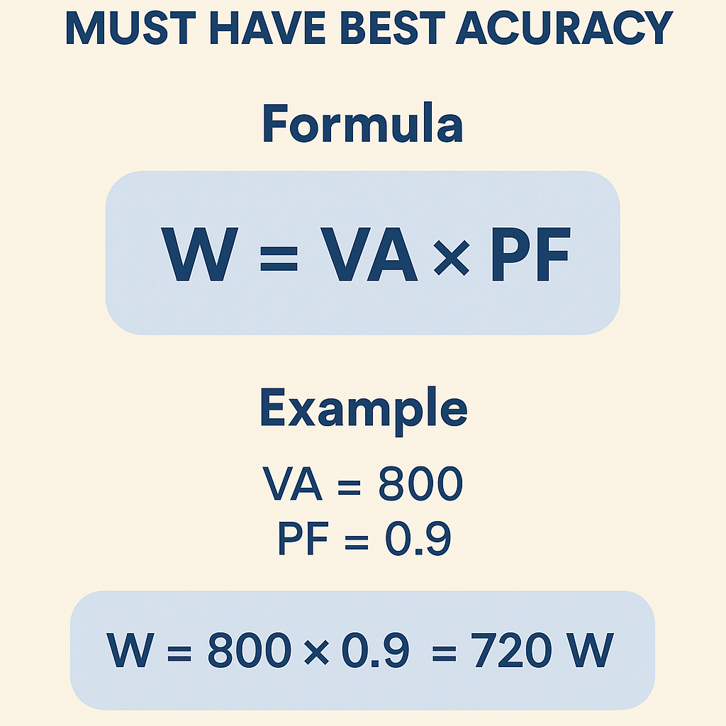
P (W) = S (VA) × pf
Where:
- S (VA) = Vrms (V) × Irms (A)
- pf = cos(phi) for purely sinusoidal waveforms, adjusted for distortion with IEEE definitions
Why accuracy matters
Design margins, thermal ratings, energy billing, generator sizing, UPS selection, and protective device coordination all depend on accurate conversion between VA and W. An underestimated active power can lead to undersized neutral conductors, overheating, and non-compliance with standards. Overestimation leads to overspecification and unnecessary cost.
Sources of error in VA-to-Watt conversion
- Power factor misestimation: Using assumed pf (e.g., 0.8 or 1.0) rather than measured pf introduces systematic error.
- Harmonic distortion: Non-sinusoidal waveforms require distortion-aware pf (IEEE 1459 definitions), otherwise conversion is wrong.
- Measurement instrument accuracy: Instrument transformers (CTs, VTs), multimeters, and power analyzers have accuracy classes and burdens.
- Phase configuration: Single-phase versus three-phase (delta/wye) conversions must use correct formulas and line/phase voltages.
- Resolution and rounding: Truncation and insufficient significant figures can bias aggregated results.
Quantifying measurement uncertainty
When converting VA to W for procurement or billing, propagate instrument error and pf uncertainty. Use root-sum-square (RSS) to combine independent uncertainties.
Example propagation formula (simplified):
u(P) ≈ P × sqrt( u(S)^2 + u(pf)^2 )
Where u(S) is relative uncertainty of apparent power (from voltage and current measurements) and u(pf) is relative uncertainty of power factor measurement. Typical instrument uncertainties: class 0.5% to 1% for power analyzers; CT errors depend on ratio and burden; VTs typical 0.1%–0.5%.
Single-phase conversion formulas and variable definitions
Primary single-phase formula reiterated with variables explained:
P (W) = Vrms × Irms × pf
Variable definitions and typical values:
- Vrms (V) — Root-mean-square voltage. Typical domestic values: 120 V (North America), 230 V (Europe).
- Irms (A) — Root-mean-square current. Typical branch currents: 1 A to 63 A in distribution panels.
- pf — Power factor (dimensionless). Typical ranges: 0.6 (inductive motor under light load) to 0.99 (well-corrected resistive loads).
Three-phase conversion formulas: balanced and unbalanced systems
Three-phase systems require specific formulas depending on configuration (balanced, symmetrical, wye/delta) and measurement points.
Balanced three-phase apparent power (line-to-line voltage VLL):
S3φ (VA) = √3 × VLL,rms × Iline,rms
Active power for balanced three-phase:
P3φ (W) = √3 × VLL,rms × Iline,rms × pf
Variable explanations and typical values:
- VLL,rms (V) — Line-to-line RMS voltage (e.g., 400 V, 480 V).
- Iline,rms (A) — Line current in each phase.
- pf — System power factor. For industrial loads, typical pf without correction ranges from 0.7 to 0.95.
Unbalanced systems and measurement strategy
For unbalanced three-phase systems, measure V and I in each phase and compute per-phase apparent and active power, then sum the active power. For each phase:
P_phase = V_phase × I_phase × pf_phase
When harmonics are present, use true-RMS instruments and follow IEEE 1459–2010 for separating active power contributions.
Harmonics, distortion power, and effective power factor
Nonlinear loads create harmonic currents. The classical cosine power factor (cos φ) is insufficient; the displacement power factor must be combined with distortion power factor. The overall pf becomes:
pf = displacement_pf × distortion_pf
Explicit relation (from IEEE):
pf = P / S where P is true active power (including harmonic contributions), S is apparent power computed from RMS values including harmonics.
Typical values:
- Displacement pf (cos φ) typical: 0.95–0.99 for synchronous loads.
- Distortion pf typical: 0.90–1.00 depending on harmonic content.
- Overall pf for heavily distorted loads: 0.6–0.9.
Design of a high-accuracy VA to Watts calculator: algorithmic considerations
To achieve best accuracy, a calculator must implement:
- True-RMS computation for voltage and current waveforms sampled at adequate bandwidth (≥10× highest harmonic of interest).
- Per-phase measurement and summation for three-phase unbalanced loads.
- Harmonic analysis (FFT or Goertzel) to compute distortion contribution and separate displacement and distortion pf.
- Instrument error modeling: include CT/VT ratio correction, phase shift, and burden effects.
- Uncertainty propagation module to report confidence intervals.
- Configurable sample rate, averaging window, and smoothing for transient vs steady-state measurements.
Sampling and anti-aliasing
Sampling theorem: sample frequency fs must exceed 2× highest frequency component selected. For power quality including up to 50th harmonic of 50 Hz (2.5 kHz), choose fs ≥ 10 kHz for margin. Use anti-aliasing filters to avoid spurious spectral content.
Tables of common conversions and reference values
| VA | pf = 1.00 (W) | pf = 0.95 (W) | pf = 0.90 (W) | pf = 0.85 (W) | pf = 0.80 (W) |
|---|---|---|---|---|---|
| 100 | 100 | 95 | 90 | 85 | 80 |
| 250 | 250 | 238 | 225 | 213 | 200 |
| 500 | 500 | 475 | 450 | 425 | 400 |
| 1000 | 1000 | 950 | 900 | 850 | 800 |
| 2000 | 2000 | 1900 | 1800 | 1700 | 1600 |
| 5000 | 5000 | 4750 | 4500 | 4250 | 4000 |
| 10000 | 10000 | 9500 | 9000 | 8500 | 8000 |
| Three-Phase VLL (V) | Line Current (A) | S (kVA) = √3·V·I | pf = 1.00 (kW) | pf = 0.90 (kW) |
|---|---|---|---|---|
| 400 | 10 | 6.93 | 6.93 | 6.24 |
| 400 | 50 | 34.64 | 34.64 | 31.18 |
| 480 | 20 | 16.63 | 16.63 | 14.97 |
| 480 | 100 | 83.16 | 83.16 | 74.84 |
| 600 | 50 | 51.96 | 51.96 | 46.76 |
| 690 | 100 | 119.49 | 119.49 | 107.54 |
Calibration, instrument transformers, and practical accuracy tips
- Use class-rated CTs and VTs: CT class 0.5 or better and VT class 0.2 minimize transformer-induced errors.
- Correct for CT ratio and polarity; include CT burdens in the instrument model.
- Perform on-site verification with a calibrated reference meter or transfer standard to establish traceability to national metrology institutes (NMI).
- Compensate for phase shift introduced by CTs and VTs when calculating active power.
- For portable meters, follow warm-up and zeroing procedures recommended by manufacturer.
Significant figures and reporting
Report power values with meaningful significant figures based on combined uncertainty. For example, if relative uncertainty is ±1.5%, report to three significant digits maximum to avoid false precision.
Two complete worked examples with full solutions
Example 1 — Single-phase lighting bank measurement
Scenario: A commercial lighting circuit is measured. Measured true-RMS voltage V = 230.2 V, measured true-RMS current I = 12.34 A, measured true active power P_meas = 2700 W reported by a calibrated meter. The meter reports pf reading, but engineering wants to compute P from VA and pf and validate.
Step 1 — Compute apparent power S:
S = V × I
Step 2 — Compute pf from measured P_meas:
pf = P / S
Step 3 — Validate calculated P using S and pf:
P_calc = S × pf = 2840.868 × 0.9504 = 2699.99 W
Step 4 — Uncertainty estimation: instrument uncertainties: voltage ±0.2%, current ±0.5%, power ±0.5% (typical). Relative uncertainty of S from V and I (RSS):
u(S) ≈ sqrt(0.002^2 + 0.005^2) = sqrt(4e-6 + 25e-6) = sqrt(29e-6) = 0.005385 ≈ 0.5385%
Assume pf uncertainty u(pf) ≈ 0.005 (0.5%). Propagate to P relative uncertainty:
u(P) ≈ sqrt(u(S)^2 + u(pf)^2) = sqrt(0.005385^2 + 0.005^2) ≈ 0.00734 = 0.734%
Absolute uncertainty on P (~2700 W): ±(0.00734 × 2700) ≈ ±19.8 W.
Conclusion: P_calc and P_meas agree within measurement uncertainty; report P = 2700 W ± 20 W, pf = 0.950 ± 0.005.
Example 2 — Three-phase motor load with harmonic content
Scenario: A three-phase motor-driven pump measured at line-to-line voltage VLL = 400 V, measured line currents I_A = 45.2 A, I_B = 46.8 A, I_C = 44.0 A. True active power measured by analyzer P_total = 28.5 kW. The analyzer also reports THD on current: THD_A = 8%, THD_B = 7.5%, THD_C = 9%.
Goal: Compute P from per-phase measurements and pf, and reconcile with P_total, accounting for harmonics.
Step 1 — Compute per-phase apparent power using line voltages and per-phase currents (assuming wye connection and balanced line voltage magnitude across phases):
We use Sphase_i = V_phase × I_phase. For a wye system V_phase = VLL / √3 = 400 / 1.73205 = 230.94 V.
Step 2 — Compute total apparent power S_total (vector sum of RMS values can also be approximated by √3·VLL·I_avg in balanced cases; here we sum per-phase):
Step 3 — Compute average power factor implied by measured P_total and S_total:
pf = P_total / S_total = 28500 / 31417.9 = 0.9071
Step 4 — Estimate effect of harmonics using current THD. Distortion power factor for each phase can be approximated:
Step 5 — Validate active power using per-phase S and pf components:
Compute per-phase product:
Step 6 — Compare with measured P_total = 28.5 kW. Agreement within ~6.5 W; thus calculation consistent. Estimate combined uncertainty from instrument specs, CTs, and harmonic estimation; typical relative uncertainty ±1.2% (~±342 W).
Conclusion: Accurate accounting for harmonics and per-phase measurements produced P_calc_total consistent with analyzer reading. Report P = 28.50 kW ± 0.34 kW, pf ≈ 0.907.
UX and calculator interface recommendations for best accuracy
For a user-facing VA-to-Watt calculator intended for engineers, include:
- Input modes: single-phase, three-phase balanced, three-phase unbalanced.
- Fields for measured V, I, P, pf, THD, CT/VT ratios, and instrument accuracy classes.
- Options for waveform type: sinusoidal vs non-sinusoidal — enable harmonic-aware calculations.
- Display of uncertainty with configurable confidence level (e.g., 95% coverage factor).
- Exportable report with per-phase breakdown, assumptions, and normative references used.
Validation and test cases for QA
- Sinusoidal resistive load where pf = 1: ensure P = S within instrument error.
- Inductive motor load with low pf: validate P derived from S × pf against direct power measurement.
- Nonlinear PWM-driven load with significant harmonics: verify harmonic-aware algorithm reproduces analyzer readings within uncertainty.
- Unbalanced three-phase cases: verify per-phase sums equal total P measured by three-phase power analyzer.
Regulatory and normative references
- IEEE Std 1459-2010 — Definitions for the Measurement of Electric Power Quantities Under Sinusoidal, Nonsinusoidal, Balanced, or Unbalanced Conditions. See: https://standards.ieee.org/standard/1459-2010.html
- IEC 61000 series — Electromagnetic compatibility (EMC) — covers harmonic emission measurements. See: https://www.iec.ch/
- IEC 60038 — Standard voltages. See: https://webstore.iec.ch/publication/2012
- NIST — Guidelines on Instrument Calibration and Traceability. See: https://www.nist.gov/
- ISO/IEC 17025 — General requirements for the competence of testing and calibration laboratories (for instrument calibration traceability). See: https://www.iso.org/standard/66912.html
Best-practice checklist for obtaining highest accuracy in VA-to-Watt conversion
- Use true-RMS metering equipment with known calibration and traceability to an NMI.
- Measure per-phase voltage and current for three-phase systems; avoid single-point assumptions for unbalanced conditions.
- Measure and include power factor and THD; do not assume pf unless validated by measurements.
- Correct for instrument transformer ratios, polarity, and phase shift.
- Document averaging period, sampling rate, and environmental conditions when measurements are taken.
- Report uncertainty and significant figures consistent with combined measurement uncertainty.
Common pitfalls and how to avoid them
- Assuming pf = 1 for cost or sizing estimates — always measure or conservatively assume lower pf and include contingency.
- Using RMS readings from basic meters that are not true-RMS for distorted waveforms — use true-RMS meters or power analyzers for nonlinear loads.
- Neglecting CT saturation and burdens during high current transients — select CTs with appropriate knee point and thermal rating.
- Reporting spurious precision — round results to reflect real uncertainty.
Performance metrics for a "must-have" accurate VA-to-Watt calculator
Metrics that define a high-quality calculator:
- True-RMS computation accuracy: ≤0.5% for voltages and currents up to specified THD.
- Power conversion agreement: <±1% against laboratory-grade power analyzers for sinusoidal loads; <±2% for typical nonlinear loads when harmonics included.
- Uncertainty reporting: automated calculation of combined standard uncertainty with configurable coverage factor.
- Traceability: calibration and algorithm traceable to IEEE/IEC definitions and NMI standards.
Further reading and authoritative resources
- IEEE Std 1459-2010 for power definitions and measurement methodology: https://standards.ieee.org/standard/1459-2010.html
- IEC 61000 series on power quality and harmonics: https://www.iec.ch/
- NIST guidelines and calibration resources: https://www.nist.gov/
- Energy Efficiency Best Practices for Power Factor Correction (Department of Energy): https://www.energy.gov/
Operational recommendations for engineers
When integrating a VA-to-Watt conversion tool into engineering workflows:
- Embed automatic retrieval of instrument specs and CT/VT configurations to reduce manual entry errors.
- Allow toggling between simplified quick estimates and detailed measurement-driven calculations.
- Include audit-trail logging of inputs, measurement timestamps, calibration certificates, and environmental conditions.
- Provide downloadable test reports compliant with ISO/IEC 17025 traceability documentation.
Summary of technical imperatives
Accurate VA-to-Watt conversion is not merely arithmetic; it requires proper measurement practice, harmonic-aware algorithms, instrument calibration, and uncertainty management. A high-accuracy calculator must combine true-RMS sampling, per-phase handling for unbalanced systems, harmonic analysis, and propagated uncertainty reporting. Adhering to IEEE and IEC measurement definitions and maintaining traceability to NMIs delivers the reliability required for engineering decisions, procurement, regulatory compliance, and energy billing.