Placement of surge protective devices near ATS affects emergency system reliability and transient protection performance.
This technical guidance compares line side versus load side SPD installation to maximize protection effectiveness.
SPD Placement Around ATS (Line Side vs Load Side) – Protection Margin and Recommended Location
Surge protective device roles in ATS-based emergency power systems
Automatic transfer switches (ATS) coordinate transfer between normal and alternate power sources. SPDs (surge protective devices) mitigate overvoltage transients caused by lightning, switching, fault arcs, and ground potential rise. In emergency systems, where loss of power or transient damage can endanger life-safety functions, SPD placement and coordination are critical for ensuring continuity and equipment survival.
Key functional objectives for SPDs in emergency circuits
- Protect switchgear, ATS contacts, and downstream life-safety loads from high-energy transients.
- Limit transient overvoltages to levels below equipment impulse withstand (Up ≤ equipment rating).
- Prevent SPD failure modes (thermal runaway, short-circuit) that could compromise emergency supply availability.
- Ensure selectivity and cascading coordination across multiple SPD stages (service entrance, distribution, local).
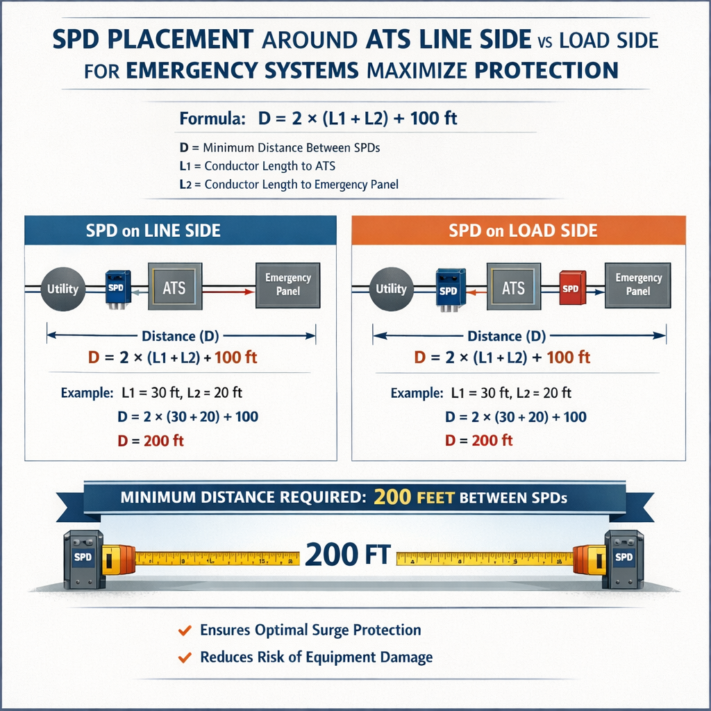
Line side vs load side SPD placement: technical trade-offs
Line-side SPDs are installed upstream of the ATS where they clamp transients coming from the utility or generator before the ATS. Load-side SPDs are installed downstream of the ATS to protect the loads and the distribution downstream from both sources. Selection criteria must consider source switching behavior, available prospective fault current, conductor routing, and maintenance isolation.
Advantages of installing SPDs on the ATS line side
- Protects ATS itself and upstream distribution equipment from utility-originating surges.
- Simplifies protection if a single SPD covers both normal and alternate sources when properly applied.
- Reduces number of downstream devices required for broad facility protection in some designs.
Advantages of installing SPDs on the ATS load side
- Protects critical loads irrespective of which source (normal or alternate) is connected.
- Reduces risk that transient energy bypasses protection due to ATS switching operations.
- Facilitates cascading protection architecture (Type 1/Type 2 coordination) close to sensitive equipment.
Standards and normative considerations
Designers must follow applicable codes and standards which dictate SPD performance, testing, and application in life-safety circuits:
- NFPA 70 (NEC): Article 700—Emergency Systems and Article 285/240 for coordination. See https://www.nfpa.org/ for code details.
- NFPA 110—Standard for Emergency and Standby Power Systems, for operational requirements and reliability.
- IEC 61643-11 / EN 61643-11—Low-voltage surge protective devices requirements and testing for Type 1/2 SPDs.
- UL 1449—Standard for safety of SPDs (United States). See https://www.ul.com.
- IEEE C62.41 and C62.45—Surge environment characterization and recommended practices for installation.
Code implications specific to emergency circuits
- NEC Article 700 requires emergency systems to transfer reliably and continue operation; any protective device must not impede this function.
- SPDs that could create a short-circuit on failure must be coordinated with upstream overcurrent protection to avoid disabling emergency circuits.
- Where SPDs are installed on the line side and provide bonding between neutral and ground, designers must verify bonding scheme compatibility per NEC and local regulations.
SPD types, classification and typical application points around an ATS
Classification commonly used in practice:
- Type 1 (or Class I): Installed at service entrance or at main distribution to handle high-energy lightning impulses—often required where external lightning exposure is high.
- Type 2 (or Class II): Installed at distribution panels and near sensitive equipment to protect against residual transients and switching surges.
- Type 3 (or Class III): Point-of-use devices for highly sensitive electronics.
| SPD Type | Typical Location Relative to ATS | Primary Function | Typical Iimp (8/20 μs) Rating | Typical Uc (Max Continuous Voltage) |
|---|---|---|---|---|
| Type 1 | Service entrance / Before ATS (line side) | Handle direct lightning and high-energy impulses | 10 kA – 100 kA per phase | 385 V (for 277/480 systems) to 600 V |
| Type 2 | Distribution boards / After ATS (load side) | Mitigate residual transients, switching surges | 5 kA – 40 kA per phase | 320 V – 600 V |
| Type 3 | Point-of-use near critical equipment | Protect electronics and control devices | 1 kA – 10 kA per phase | 150 V – 320 V |
Electrical calculations and formulas for SPD selection and placement
Below are core formulas used for design decision-making. Each formula is presented in plain markup and is followed by variable explanations and typical values.
1) Prospective short-circuit current at SPD location
Formula:
Ipsc = Un / Zs
Where:
- Ipsc = prospective short-circuit current (A)
- Un = nominal line-to-line or line-to-neutral voltage depending on calculation (V)
- Zs = source plus conductor impedance to the SPD point (Ω)
Typical values:
- Un: 480 V (three-phase) or 277 V (line-to-neutral) for many commercial/industrial emergency systems.
- Zs: 0.005 Ω to 0.05 Ω depending on transformer impedance and upstream fault level.
Example: For a 480 V system with Zs = 0.01 Ω, Ipsc = 480 / 0.01 = 48,000 A (48 kA).
2) Voltage drop across source impedance during surge
Formula:
Vdrop = I × Z
Where:
- Vdrop = voltage across impedance (V)
- I = transient current value (A)
- Z = line/source impedance (Ω)
Typical values: If I = 10 kA and Z = 0.01 Ω, Vdrop = 10,000 × 0.01 = 100 V. This additional voltage modifies the effective clamp and must be considered when ensuring Up ≤ equipment withstand.
3) Cascaded SPD coordination rule of thumb
When using upstream and downstream SPDs, the cumulative let-through must be less than downstream equipment impulse withstand.
Rule (approximate): Ueq = Uupstream + Udownstream
Where:
- Ueq = equivalent residual voltage at the equipment terminals (V)
- Uupstream = residual voltage left after upstream SPD clamping (V)
- Udownstream = residual voltage of downstream SPD (V)
Design target: Ueq ≤ equipment impulse withstand voltage (e.g., 1.2/50 μs withstand). Typical targets: for 120 V electronics, keep Ueq ≤ 800 V; for 277 V lighting gear, Ueq ≤ 1500 V.
4) Energy (Joule) estimate for a surge waveform
Approximate energy for an 8/20 μs current waveform is evaluated using the I2t integral:
I2t = ∫ i(t)2 dt
Where:
- I2t = Joule integral over time (A2·s)
- i(t) = instantaneous surge current (A)
Typical practice: SPD manufacturers provide Iimp (8/20 μs) ratings and associated I2t values; use those manufacturer's curves for energy handling verification.
Practical design methodology: step-by-step checklist
- Define critical loads and required reliability for emergency circuits (NFPA 110 categories and runtime requirements).
- Characterize surge environment (lightning exposure, industrial switching, VFDs) and identify likely transient sources.
- Calculate prospective short-circuit current at candidate SPD locations for both normal and alternate sources using Ipsc = Un / Zs.
- Select SPD types: usually Type 1 at service for lightning-prone sites, Type 2 at distribution panels, and Type 3 near sensitive electronics.
- Determine whether SPDs are required on both line sides feeding the ATS or only on load side depending on transfer scheme and site risk.
- Design bonding and earthing to minimize loop impedance and ensure SPD operating reference is consistent with equipment earthing.
- Coordinate SPD response and upstream overcurrent devices to avoid nuisance tripping or failure modes that could remove emergency power.
- Document maintenance, replacement intervals, and remote status monitoring for SPDs in emergency circuits.
Installation best practices specific to ATS systems
- Keep SPD conductor lengths as short as possible to minimize inductive voltage rise under high di/dt transient currents.
- Use heavy gauge copper for SPD bonding conductors; run in parallel if necessary to reduce impedance.
- Install SPDs so they protect both phases and neutral where required; neutral handling must follow manufacturer instructions and local code.
- Avoid placing a single SPD on the line side only if the ATS alternator source can feed surges from its own generator; consider SPDs on each source or on the load side downstream of the ATS.
- Where SPDs are installed line side, ensure they are rated to withstand the highest expected prospective current from either source and the switching transients associated with the ATS operation.
- Provide means to isolate and replace SPDs without removing critical loads from service if possible (e.g., parallel redundant SPDs or bypass switches in non-critical locations).
| Design Item | Typical Requirement | Rationale |
|---|---|---|
| SPD conductor length | < 0.5 m (recommended) from SPD to protected bus | Minimize series inductance and additional let-through voltage |
| Bonding conductor | Cu AWG 6 to AWG 2 / parallel runs for high-energy sites | Reduce impedance; meet short-circuit withstand and thermal limits |
| Testing & monitoring | Remote status alarm, periodic visual and electrical checks (annual) | Ensure functionality for life-safety loads and compliance documentation |
| SPD replacement criteria | Replace after any event above specified Isc endurance or visible degradation | Prevent latent degradation that could reduce protection during critical transfer |
Real-case example 1: Hospital emergency generator ATS — detailed solution
Scenario summary: A hospital has a 480/277 V, three-phase distribution system with an ATS connecting utility (normal) and on-site generator (alternate). The ATS feeds emergency distribution panels serving life-safety loads. The site is in a moderate lightning region. Design objective: Select SPD locations and devices to ensure life-safety loads remain within equipment impulse withstand during surges while maintaining ATS reliability.
Given data and assumptions
- System nominal voltage ULL = 480 V (line-to-line); ULN = 277 V.
- Prospective short-circuit current at main service: 50 kA (utility available).
- Generator short-circuit contribution at bus after start-up: 10 kA.
- ATS located at main emergency distribution entry.
- Critical equipment impulse withstand: 2.5 kV line-to-neutral (for selected lighting & control gear).
- Preferred SPD configuration must avoid taking ATS out of service on SPD failure.
Design steps and calculations
- Identify candidate SPD mounting points: (A) Line side before ATS (service entrance), (B) Load side immediately downstream of ATS, and (C) local distribution panels.
- Calculate prospective short-circuit for SPD at line side: given 50 kA; select an SPD rated for at least the available Ipsc or ensure upstream protective devices will limit fault current through SPD on failure. Choose Type 1 SPD with Iimp rating 40 kA – 60 kA per phase and UL1449 Category C for service entrance.
- Assess generator-side surges: generator switching transients and possible ground potential rise require SPDs on generator source as well. Install a symmetrical Type 1/2 on generator output sized for 10 kA to 20 kA.
- Evaluate residual voltage at load if only upstream SPDs installed: upstream Type 1 may clamp but inductive voltage rise on short conductor runs to ATS could leave residual pulses exceeding equipment withstand. Therefore add Type 2 SPDs on load side near ATS output to act as secondary stage and reduce residual let-through.
- Coordination target: Ensure combined residual voltage Ueq ≤ 2.5 kV. If upstream SPD Up ≈ 1.2 kV and downstream SPD Up ≈ 600 V, Ueq ≈ 1.8 kV which meets requirement.
Selected devices and placement
- Service entrance: Type 1 SPD, Iimp=60 kA 8/20 μs, Uc appropriately rated for 480 V system.
- Generator output: Type 1/2 SPD, Iimp=20 kA.
- ATS load side (immediately downstream): Type 2 SPD, Up ≈ 600 V, Iimp=20 kA.
- Local distribution boards for sensitive control equipment: Type 3 point-of-use SPDs.
Verification calculations (simplified)
Assume upstream SPD residual voltage Uup ≈ 1200 V under specified surge. Downstream SPD residual Udown ≈ 600 V.
Equivalent residual at equipment: Ueq = Uup + Udown = 1200 + 600 = 1800 V < 2500 V. Acceptable.
Operational and reliability considerations
- Install remote alarm contacts for SPDs on ATS line and load sides to notify maintenance on degradation.
- Ensure SPD failure modes are fail-open (preferred) or fused with coordinated upstream overcurrent protection to avoid unplanned loss of emergency power.
- Document maintenance and replacement thresholds per NFPA 110 and manufacturer's guidance.
| Location | SPD Type | Iimp (8/20 μs) | Expected Up (V) |
|---|---|---|---|
| Service entrance (line side) | Type 1 | 60 kA | ~1200 V |
| Generator output | Type 1/2 | 20 kA | ~1000 V |
| ATS load side | Type 2 | 20 kA | ~600 V |
Real-case example 2: Data center transfer switch protecting critical UPS loads
Scenario summary: A medium-sized data center uses two utility feeds with an ATS and an on-site diesel generator for redundancy. Critical IT equipment is downstream of UPS systems which are fed from emergency bus via ATS during utility outages. Goal: minimize transient propagation through ATS to UPS input and ensure UPS and control electronics are not exposed to damaging surge levels.
Given data and assumptions
- System voltage: 208Y/120 V three-phase wye.
- UPS input transient withstand: 1.5 kV line-neutral.
- Prospective short-circuit at service: 25 kA. Generator contribution 5 kA.
- UPS sensitivity and downstream equipment critical; minimal downtime tolerance.
Design approach
- Because UPS equipment is highly sensitive, place Type 2 SPDs at UPS input (load side) with low Up (≤ 600 V) as the primary protective layer.
- Due to multiple upstream sources, install Type 1 SPDs on each incoming service and generator output to manage high-energy external impulses.
- Ensure short SPD conductor runs from SPD to UPS input bus—preferably < 0.3 m—to minimize inductive voltage additions during transient currents.
- Specify remote monitoring for all SPDs and redundant SPD design near the UPS to permit replacement without taking UPS offline if possible.
Quantitative check
Assume upstream SPD Up ≈ 900 V and point-of-use SPD Up ≈ 500 V. Equivalent residual Ueq ≈ 1400 V < UPS withstand 1500 V. Therefore coordinate devices such that combined residual remains below 1.5 kV during worst-case surge.
Installation details
- Each utility feed: Type 1 SPD rated for 40 kA 8/20 μs.
- Generator feed: Type 1/2 SPD rated 20 kA.
- UPS input: Type 2 SPD, Up ≤ 500 V, Iimp 20 kA, located within 0.3 m of UPS input bus.
- Conductor sizing: bonding conductors AWG 4 minimum; parallel bonding for critical runs.
| Item | Selected Value | Reason |
|---|---|---|
| Upstream SPD rating | 40 kA (8/20 μs) | Manage moderate external lightning environment and utility transients |
| Point-of-use SPD Up | ≤ 500 V | Ensure UPS input stays below 1.5 kV withstand |
| Conductor length to UPS | < 0.3 m | Minimize inductive voltage from di/dt |
Maintenance, testing and life-cycle management
- Periodic visual inspection and remote status check monthly or per facility policy.
- Use SPD status contacts tied into building management or emergency monitoring system to flag degradation.
- Replace SPDs after major surge events where their rated energy has been consumed or per manufacturer recommended cycles.
- Record event logs and I²t exposure history when available; for critical systems, maintain spare SPDs on-site for rapid replacement.
Risk analysis: failure modes and mitigation
- SPD fails short-circuit: Coordinate with upstream protective devices (fuses or breakers) to ensure SPD fault will trip upstream overcurrent without removing the ATS supply when possible.
- SPD fails open or becomes high impedance: Downstream devices lose protection—mitigate with cascade protection and redundancy.
- Thermal runaway on repeated events: select SPDs with thermal disconnection or thermal fusing features per UL 1449.
Recommended practice summary for maximizing protection
- Apply an overall cascaded protection strategy: Type 1 on each source, Type 2 on ATS load side, Type 3 at point-of-use for the most sensitive devices.
- Short bonding conductors and low inductance routing around ATS minimize additional let-through voltages.
- Provide SPDs on both sources feeding the ATS where practicable, or ensure robust load-side SPDs where dual-source SPD placement is impractical.
- Coordinate SPD residuals against equipment impulse withstand and verify with combined Up calculations.
- Ensure SPD failure will not compromise emergency power availability; use redundant devices or coordinated fusing.
References and further reading
- NFPA 70, National Electrical Code (NEC) — particularly Article 700 on Emergency Systems. https://www.nfpa.org/
- NFPA 110, Standard for Emergency and Standby Power Systems. https://www.nfpa.org/
- IEC 61643-11, Surge protection devices connected to low-voltage power systems. https://www.iec.ch/
- UL 1449, Surge Protective Devices. https://www.ul.com/
- IEEE C62.41.2, Guide on Surge Environment in Low-Voltage AC Power Circuits. IEEE Xplore overview: https://standards.ieee.org/
- Manufacturer technical application notes (consult SPD vendors for exact Up, Iimp, and I2t values).
Final engineering considerations
SPD placement around an ATS is not one-size-fits-all. Best practice frequently combines protection at sources and the load side with tight conductor routing, clear coordination plans, and documented maintenance. For emergency systems, the overriding constraint is that protective devices must not impair the transfer of power or introduce single points of failure. Use standards-based selection, model worst-case combined residual voltages, and validate with manufacturer test data and field measurements.