This article explains technical neutral resistor sizing and the necessary calculations for grounding control systems
Engineers require precise formulas, energy limits, protective devices, and normative references for safe implementation today
Neutral Grounding Resistor (NGR) Sizing Calculator
Purpose and scope of this technical guidance
This document provides a detailed, engineering-grade methodology for selecting and verifying neutral grounding resistor (NGR) values, power ratings, and protective coordination. It addresses steady-state continuous duty, intermittent limiting, thermal energy absorption, fault timing, secondary protective devices, and practical implementation constraints for low and medium voltage systems.
Fundamentals of neutral resistor sizing
Neutral grounding resistors are used to limit single-line-to-ground fault current to a controlled value, reducing damage and transient overvoltages while enabling selective protection and minimizing arc-flash hazards. The core parameters are system phase-to-ground voltage, desired ground-fault current limit, resistor continuous power dissipation, and transient energy absorption capability for the expected fault clearing time.
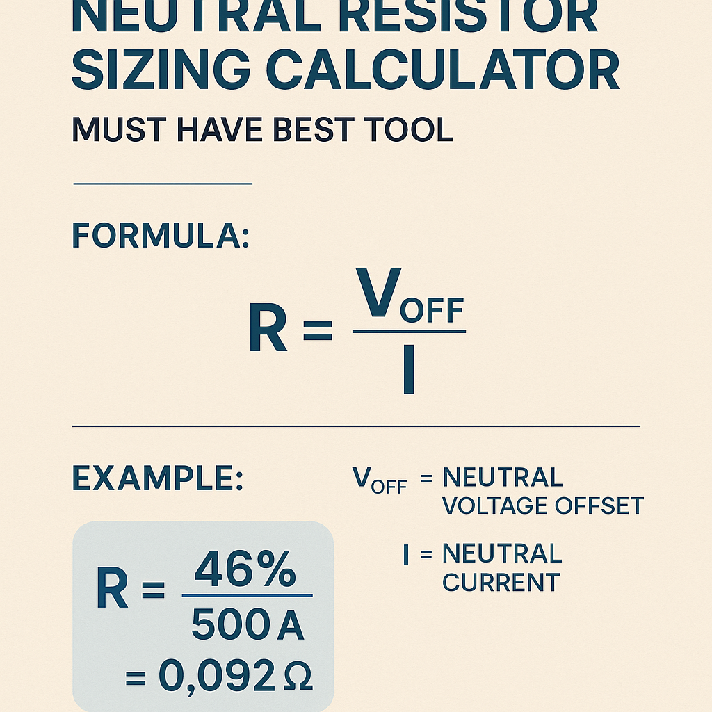
Key formulas (HTML text-only)
Variable definitions and typical values
- R — Resistor value (ohm, Ω). Typical range: 0.1 Ω to several kilo-ohms depending on system voltage and desired Ig.
- Vph — Phase-to-ground voltage (volts, V). Typical low-voltage examples: 120 V, 208 V, 240 V, 277 V, 347 V, 480 V (line-to-line values require division by √3 for phase-to-ground).
- Ig — Desired ground-fault current (amperes, A). Typical targeted limits: 5 A to 1200 A depending on protection scheme and system size.
- P — Continuous power dissipation in resistor (watts, W). Typical manufacturer ratings: 1 kW to 200 kW for continuous duty; transient ratings significantly higher for short durations.
- E — Energy absorbed during fault (joules, J). Must be compared against resistor energy rating for the clearing time.
- t — Fault clearing time (seconds, s). Typical protective device clearing times: fuses (cycles to seconds), relays (0.1–1 s), breaker trip delays (0.05–2 s).
System voltage relationships and typical phase-to-ground values
| System (Line-to-Line) | Configuration | Phase-to-Ground (Vph) | Common Use |
|---|---|---|---|
| 120/208 V | 3-phase wye | 120 V | Commercial lighting, small motors |
| 240/415 V | 3-phase wye | 240 V | Industrial low-voltage distribution |
| 277/480 V | 3-phase wye | 277 V | Commercial/industrial power and lighting |
| 3300 V | 3-phase wye | 1905 V | Medium-voltage plant feeders |
| 11 kV | 3-phase wye | 6350 V | Utility/large industrial MV distribution |
| 13.8 kV | 3-phase wye | 7976 V | Substation feeders |
Design targets and practical constraints
When choosing Ig (target fault current) and resistor parameters, engineers balance several objectives:
- Limit Ig to reduce thermal/mechanical fault damage and restrain transient overvoltages.
- Enable fault detection and selective protection (relay pick-up thresholds must exceed residual currents from distributed sources).
- Ensure resistor energy absorption capability for the maximum fault clearing time without damage.
- Provide continuous duty if required (some systems require continuous limited neutral grounding).
- Consider service conditions: ambient temperature, enclosure IP rating, cooling (forced air, water-cooled), and maintenance access.
Typical target Ig ranges and rationale
- High resistance grounding (HRG): Ig ≤ 10 A — used to limit damage and allow continued operation on one-phase ground for extended periods.
- Effective resistance grounding: Ig ~ 10–300 A — used where limited fault current aids quick clearing while limiting damage.
- Solidly grounded: no resistor — Ig equals available fault current (undesirable for arc-flash severity control in many cases).
Tables of common sizing outcomes
Below are common computed resistor values and power/energy consequences for standard voltages and target Ig values. Use these for quick reference during preliminary design.
| System Vph (V) | Target Ig (A) | Calculated R (Ω) | Continuous P = Ig^2·R (W) | Energy for t = 5 s (J) |
|---|---|---|---|---|
| 120 | 10 | 12.00 | 1,440 | 7,200 |
| 120 | 50 | 2.40 | 6,000 | 30,000 |
| 277 | 50 | 5.54 | 13,850 | 69,250 |
| 277 | 400 | 0.6925 | 110,800 | 554,000 |
| 6350 | 100 | 63.50 | 635,000 | 3,175,000 |
| 6350 | 20 | 317.50 | 127,000 | 635,000 |
| Resistor Type | Continuous Rating | Short-Time Rating | Typical Applications |
|---|---|---|---|
| Resistor bank, air-cooled | 1 kW–50 kW | Up to 500 kW for seconds | LV industrial distribution |
| Water-cooled resistor | 50 kW–>500 kW | High energy absorption for MV systems | Medium and large substations |
| Ceramic resistor, enclosed | 100 W–10 kW | Up to 50× rated for short durations | Control panels and service entrances |
Selecting resistor value: formula application and verification
Step 1: Determine system phase-to-ground voltage Vph. Step 2: Choose desired Ig based on protection and operating philosophy. Step 3: Compute R = Vph / Ig. Step 4: Compute continuous power P = Ig^2 * R. Step 5: Confirm resistor thermal capacity or specify transient energy rating E = Ig^2 * R * t for maximum clearing time t.
Important verification checks
- Ensure R value is manufacturable and available in standard or custom configurations.
- Check continuous P against resistor cooling method and ambient derating.
- Verify E for maximum credible fault clearing time including backup device delays and fuse clearing characteristics.
- Coordinate residual-current sensing relays and digital protection setpoints to detect and clear faults reliably at the chosen Ig.
- Address seismic, enclosure, and maintenance considerations for the physical resistor installation.
Real-world worked example 1 — Low-voltage commercial building
Problem statement: A 480Y/277 V distribution transformer supplies a commercial building. The design policy requires limiting single-line-to-ground fault current to 400 A to reduce arc-flash severity and allow existing relays to detect and clear faults. Determine resistor value, continuous dissipation, and energy for a 0.5 second clearing time. Verify an appropriate resistor selection.
Given data
- System: 480Y/277 V (Vph = 277 V)
- Target ground-fault current Ig = 400 A
- Fault clearing time t = 0.5 s (relay + breaker)
- Ambient: 40 °C, indoor ventilated enclosure
Calculation steps
Compute resistor value:
Compute continuous power dissipation (if fault persisted indefinitely):
Interpretation and selection
- The continuous power 110.8 kW indicates the resistor cannot carry 400 A continuously without heavy cooling; the system relies on short fault clearing time.
- Energy 55.4 kJ for 0.5 s must be within the resistor's short-time thermal rating; many air-cooled resistor banks can absorb this energy if specifically designed with thermal mass or forced cooling, but confirm manufacturer data.
- Choose a resistor rated for at least 0.6925 Ω (tolerance ±1–5%), and a short-time energy rating ≥ 60 kJ with recommended cooling and enclosure. Provide remote monitoring of temperature or fusing to prevent sustained faults.
- Coordinate relay pick-up: residual current detector should have detection threshold below 400 A but above normal unbalanced current. Adjust settings to ensure reliable trip within specified t.
Real-world worked example 2 — Medium-voltage industrial plant
Problem statement: An industrial plant has a 11 kV wye distribution with a neutral accessible for grounding. Plant safety policy mandates limiting ground-fault current to 100 A to prevent equipment damage and allow temporary operation while investigating faults. Determine resistor sizing and energy absorption for a maximum backup clearing time of 5 seconds.
Given data
- System: 11 kV line-to-line wye. Vph = 11,000 / √3 = 6350 V.
- Target Ig = 100 A
- Maximum clearing time t = 5 s (backup fuse or manual isolation may take longer, so design to this worst-case duration)
- Resistor cooled in water-cooled cabinet (higher continuous dissipation possible)
Calculation steps
Compute resistor value:
Compute continuous power dissipation:
Interpretation and selection
- Continuous dissipation of 635 kW cannot be permitted without heavy-duty water cooling and heat rejection infrastructure; therefore design intent is that resistor will carry Ig only during transient fault condition, cleared within t = 5 s.
- Energy absorption requirement of ≈3.175 MJ is significant and requires a resistor specifically designed for multi-second absorption with forced water cooling or very large thermal mass.
- Select a water-cooled neutral resistor assembly rated for 63.5 Ω and able to absorb ≥3.5 MJ with controlled temperature rise and fail-safe protective interlocks.
- Design protective coordination: an upstream protective device (e.g., relay + breaker) must clear within the assumed t; consider local temperature monitoring and automatic bypass if clearing is delayed beyond safe energy absorption limits.
Protective device coordination and fuse selection
Neutral resistors often require coordination with fuses, relays, and circuit breakers. Fuses may be used to protect resistors from prolonged faults; however, fuse selection must consider the resistor I2t energy rating and desired clearing time.
Practical coordination steps
- Establish the maximum allowed energy Emax the resistor can absorb (from manufacturer).
- Compute expected energy E = Ig^2 * R * t for likely clearing times.
- Select protective device that clears the fault within time t such that E ≤ Emax with margin (typically 25–50% margin).
- If fuses are used, consult fuse manufacturer I2t curves to ensure let-through energy is below resistor capability; use current-limiting fuses where appropriate.
- Include redundant protective schemes (e.g., local temperature monitor, overcurrent lockout) to prevent multiple unsuccessful clearing attempts.
Thermal design considerations
Resistor thermal behavior is governed by mass, specific heat, convection conditions, and enclosure. For short-duration faults, the energy absorption capability is primarily dependent on thermal mass and heat capacity; for long-duration or continuous duty, steady-state heat removal capacity is critical.
Empirical thermal relations
Temperature rise approximation for adiabatic energy absorption (short time, negligible heat loss):
Where:
- ΔT — Temperature rise (°C)
- E — Absorbed energy (J)
- m — Mass of resistor element (kg)
- c — Specific heat capacity (J/(kg·°C)), typical for steel ≈ 460 J/(kg·°C), ceramics vary 800–1000 J/(kg·°C)
Designers must ensure ΔT does not exceed material limits or insulation class ratings.
Installation, maintenance, and commissioning checks
- Verify resistor measured value with precision ohmmeter at ambient temperature; adjust for temperature coefficient if specified.
- Confirm mechanical fastening, vibration isolation, grounding of resistor enclosure, and clearances per applicable electrical standards.
- Integrate temperature sensors, status indicators, and local disconnects accessible for maintenance personnel.
- Perform a simulated application test where allowed: apply equivalent limited current for short intervals to verify thermal behavior and protective trip coordination.
- Document the as-built resistor nominal R, tolerances, energy rating, and manufacturer maintenance recommendations in the single-line diagram and maintenance manual.
Standards, norms, and authoritative references
Design and selection should reference the following authoritative documents and guides:
- IEEE Std 142™-2007, "IEEE Green Book" — Grounding of Industrial and Commercial Power Systems. https://standards.ieee.org/standard/142-2007.html
- IEEE Std 141 (Red Book) and IEEE Std C37 series — Protection and coordination of power systems. https://www.ieee.org/
- NEC (NFPA 70) — National Electrical Code requirements for grounding and wiring methods. https://www.nfpa.org/NEC
- IEC 60364 — Electrical installations of buildings — grounding and earthing practices. https://www.iec.ch/
- IEC 60909 — Short-circuit currents in three-phase systems (for available fault current estimation). https://www.iec.ch/
- Manufacturer technical datasheets and whitepapers on neutral grounding resistors (ABB, Schneider Electric, Siemens). Example: ABB technical guide on earthing resistors. https://new.abb.com/
Common pitfalls and risk mitigations
- Assuming short clearing times without verifying protective device performance — always verify relay settings and breaker capability under actual system conditions.
- Neglecting ambient and enclosure derating — high ambient or poor ventilation reduces continuous and short-time ratings.
- Inadequate energy margin — specify resistor energy rating with significant margin over worst-case calculations.
- Ignoring system unbalance and harmonic content — these factors affect residual currents and may impact detection.
- Failing to document and label NGRs and protective settings — critical for maintenance and troubleshooting.
Implementation checklist for neutral grounding resistor projects
- Establish operational policy: continuous HRG, intermittent limiting, or solid grounding.
- Determine system Vph and maximum available fault current without resistor.
- Choose target Ig with protection and continuity objectives.
- Compute R, P, and E for credible clearing times; select appropriate resistor type (air/water cooled, bank, ceramic).
- Specify and size protective devices (relays, breakers, fuses) ensuring I2t coordination.
- Design resistor enclosure, cooling system, temperature monitoring, and alarms.
- Conduct factory acceptance testing (FAT) and site commissioning tests; verify measured resistance and short-time behavior.
- Include maintenance schedule, spare parts list, and replacement considerations in O&M manuals.
Appendix: Reference tables for quick engineering checks
| Example Vph (V) | Ig (A) | R (Ω) | P (kW) | E for 1 s (kJ) |
|---|---|---|---|---|
| 120 | 5 | 24.00 | 1.44 | 1.44 |
| 240 | 20 | 12.00 | 4.80 | 4.80 |
| 277 | 100 | 2.77 | 27.7 | 27.7 |
| 480 (Vph ≈ 277) | 400 | 0.6925 | 110.8 | 110.8 |
| 6350 | 50 | 127.00 | 317.5 | 317.5 |
Further reading and manufacturer technical resources
For detailed product selection, thermal modeling, and factory testing protocols consult manufacturer technical catalogs. Typical resources include application notes on NGR design, short-time energy tables, I2t coordination guides, and case studies demonstrating installations in harsh environments.
Final engineering recommendations
- Always perform a complete short-circuit and protection coordination study considering the NGR in place; update single-line diagrams accordingly.
- Specify explicit energy and continuous ratings when procuring resistors; verify through FAT and site commissioning.
- Implement monitoring, interlocks, and fail-safe arrangements to avoid prolonged exposure to thermal stress and to ensure personnel safety.
- Maintain alignment with applicable standards (IEEE, IEC, NFPA) and obtain vendor support for complex MV and HV systems.
Standards and normative references
Key normative documents that govern grounding practices, short-circuit calculations, and safety include:
- IEEE Std 142™-2007 — Grounding of Industrial and Commercial Power Systems. https://standards.ieee.org/standard/142-2007.html
- IEC 60364 — Low-voltage electrical installations. https://www.iec.ch/
- IEC 60909 — Short-circuit currents. https://www.iec.ch/
- NFPA 70 — National Electrical Code (NEC) for installations in the United States. https://www.nfpa.org/NEC
- Manufacturer application notes: ABB, Schneider Electric, Siemens product technical guides (seek product-specific NGR datasheets).
Adherence to these methods ensures safe, reliable, and serviceable neutral grounding resistor installations. Always engage protection engineers and manufacturers early in the design process to verify assumptions and obtain tested, certified hardware for the specified duty.