This technical guide explains converting kilowatts to amperes accurately for practical electrical engineering applications today.
Includes formulas, tables, examples, regulatory references, and affordable calculator recommendations for field use and maintenance.
kW to Amps Technical Calculator — Affordable Presets
Fundamental concepts for converting kW to amps
Understanding the relationship between electrical power (kW), voltage (V), current (A), and power factor (PF) is essential for accurate conversions. The convertible quantity for many practitioners is apparent power expressed in volt-amperes (VA) versus real power in watts (W).
Basic electrical relationships and units
The primary physical law used is the power equation. For direct conversion from kilowatts to amperes, use the appropriate form depending on whether the system is single-phase or three-phase.
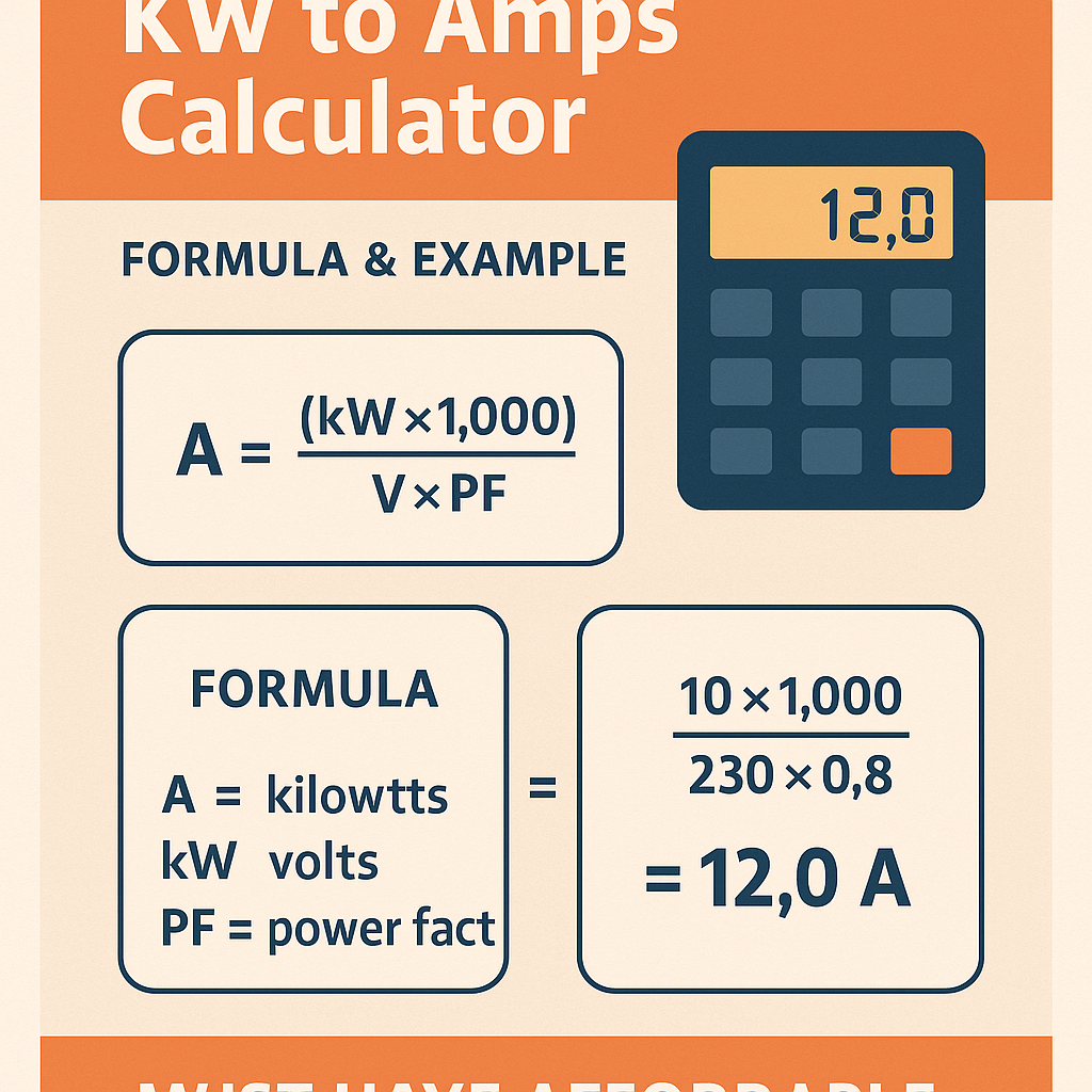
Single-phase: I (A) = (P (kW) × 1000) / (V (V) × PF)
Where:
- P (kW) = Active power in kilowatts. Typical values: 0.5 kW (small appliance), 1–10 kW (residential loads), 50–300 kW (commercial/industrial equipment).
- V (V) = Line-to-line or line-to-neutral voltage depending on wiring. Typical single-phase voltages: 120 V (North America), 230 V (Europe/worldwide).
- PF = Power factor (dimensionless). Typical PF: 0.6–0.9 for motors under varying load, 0.95–1.0 for resistive heating or ideal loads.
Three-phase (balanced): I (A) = (P (kW) × 1000) / (√3 × V (V) × PF)
Where:
- √3 ≈ 1.732 (accounts for three-phase phasor geometry).
- V (V) = Line-to-line voltage for three-phase systems. Typical voltages: 208 V, 400 V, 415 V, 480 V, 600 V.
- Other variables as above.
How power factor and efficiency influence current calculations
Power factor reduces the portion of apparent power that contributes to useful work. A low PF increases current for the same kW, affecting conductor sizing and thermal limits.
- Apparent power S (kVA) = P (kW) / PF.
- Reactive power Q (kvar) relates to PF through Q = P × tan(arccos(PF)).
- Motor efficiency (η) impacts input kW: P_input = P_output / η. Always use input power when calculating supply current.
Formulas for auxiliary corrections and efficiency
Accounting for efficiency: P_input (kW) = P_output (kW) / η
Where η is motor or inverter efficiency (typical 0.85–0.98 depending on equipment).
Complete three-phase current with efficiency considered:
Extensive tables: common kW-to-amps conversions
The following tables show representative conversions for commonly used voltages and power factors. Use them for quick estimation and verification of calculator outputs.
| kW | 120 V, PF=1 (A) | 120 V, PF=0.8 (A) | 230 V, PF=1 (A) | 230 V, PF=0.8 (A) |
|---|---|---|---|---|
| 0.5 | 4.17 | 5.21 | 2.17 | 2.71 |
| 1 | 8.33 | 10.42 | 4.35 | 5.44 |
| 2 | 16.67 | 20.83 | 8.70 | 10.87 |
| 3 | 25.00 | 31.25 | 13.04 | 16.30 |
| 5 | 41.67 | 52.08 | 21.74 | 27.17 |
| 10 | 83.33 | 104.17 | 43.48 | 54.35 |
| 20 | 166.67 | 208.33 | 86.96 | 108.70 |
| 50 | 416.67 | 520.83 | 217.39 | 271.74 |
| 100 | 833.33 | 1041.67 | 434.78 | 543.48 |
| kW | 208 V 3ϕ, PF=1 (A) | 208 V 3ϕ, PF=0.9 (A) | 400 V 3ϕ, PF=1 (A) | 400 V 3ϕ, PF=0.9 (A) | 480 V 3ϕ, PF=1 (A) | 480 V 3ϕ, PF=0.9 (A) |
|---|---|---|---|---|---|---|
| 1 | 2.78 | 3.09 | 1.44 | 1.60 | 1.20 | 1.33 |
| 5 | 13.45 | 14.94 | 7.21 | 8.01 | 6.00 | 6.67 |
| 10 | 26.90 | 29.87 | 14.43 | 16.02 | 12.01 | 13.33 |
| 20 | 53.80 | 59.73 | 28.86 | 32.04 | 24.03 | 26.67 |
| 50 | 134.50 | 149.33 | 72.15 | 80.10 | 60.07 | 66.67 |
| 100 | 269.00 | 298.67 | 144.30 | 160.20 | 120.14 | 133.33 |
| 150 | 403.50 | 448.00 | 216.45 | 240.30 | 180.21 | 200.00 |
| 300 | 807.00 | 896.00 | 432.90 | 480.60 | 360.43 | 400.00 |
| 500 | 1345.00 | 1493.33 | 721.50 | 801.00 | 600.72 | 666.67 |
Step-by-step calculation workflow for a kW to amps calculator
- Define system type: single-phase or three-phase.
- Obtain nominal voltage: use measured or system-rated voltage (V).
- Measure or specify real power P (kW) required at input (account for efficiency if necessary).
- Obtain or estimate power factor (PF). For unknown loads, use conservative PF (0.8 for motors starting, 0.9–0.95 for power electronics).
- Apply the relevant formula and compute current I (A).
- Round results according to standards and select protective devices or conductors using regulatory ampacity tables and safety margins.
Checklist for accurate calculator outputs
- Use input power (including losses), not mechanical output power.
- Include power factor for non-resistive loads.
- Adjust for supply voltage tolerance and harmonics where necessary.
- Apply applicable correction factors (temperature, grouping, insulation type) when sizing conductors.
Real-world examples with full calculations and interpretations
Example 1 — Single-phase residential load
Scenario: Calculate the current draw for an electric water heater rated 4.5 kW connected to a 230 V single-phase supply. The heater is resistive, so PF ≈ 1. Efficiency is effectively 100% for conversion of electrical energy to heat.
Step 1 — Identify parameters:
- P = 4.5 kW
- V = 230 V (single-phase)
- PF = 1.00 (resistive load)
Step 2 — Apply the single-phase formula:
Compute: I ≈ 19.57 A
Interpretation:
- Nominal current ≈ 19.6 A. Select a protective device and conductor with suitable ampacity (typically a 20 A breaker and minimum 2.5 mm² copper conductor could be marginal depending on installation rules; verify with local code and derating factors).
- If installation temperatures or conductor bundling require derating, use the next standard breaker size (e.g., 25 A) and an appropriate conductor cross-section.
Example 2 — Three-phase industrial motor including efficiency and PF
Scenario: A three-phase induction motor delivers 150 kW mechanical output. Motor efficiency η = 0.94 and power factor PF = 0.92 at rated load. The supply is 400 V line-to-line. Compute supply current.
Step 1 — Determine input electrical power:
P_input ≈ 159.574 kW
Step 2 — Apply three-phase formula:
Compute denominator: 1.732 × 400 × 0.92 ≈ 637.184
Compute numerator: 159574
I ≈ 250.46 A
Interpretation and sizing considerations:
- Nominal current ≈ 250.5 A. Protective device and conductor must be sized per local code (NEC, IEC, or national standard). For example, select a motor starter and feeder sized for locked-rotor and starting current, typically multiple of rated current.
- Account for starting/inrush currents. Large motors may require reduced-voltage starters, soft starters, or VFDs for acceptable mains impact.
- Verify conductor ampacity with temperature and grouping correction factors, and select appropriate protective devices (fuses, MCCB) with coordination studies.
Example 3 — Three-phase renewable inverter supplying continuous 50 kW
Scenario: A three-phase photovoltaic inverter outputs 50 kW AC continuously at 480 V. The inverter's efficiency η = 0.98 and PF is commanded to 0.99. Determine supply-side current for cable sizing.
Step 1 — Compute inverter AC output input correction (if necessary): for current draw on downstream AC, use P_output and PF (efficiency relates to DC inputs). For supply current, use P_output directly if inverter outputs specified AC power.
Denominator ≈ 1.732 × 480 × 0.99 ≈ 822.14
I ≈ 60.84 A
Interpretation:
- Nominal current ≈ 61 A. Select protective device and conductor per standard, considering continuous operation (some codes require sizing at 125% for continuous loads).
- If continuous classification applies, conductor and breaker selection must account for 125% rule: design current = 60.84 × 1.25 ≈ 76.05 A; choose nearest standard device and conductor.
Practical calculator features and affordable deployment options
A useful, affordable kW to Amps calculator for professionals should include:
- Selection for single-phase or three-phase systems.
- Inputs for P (kW), voltage (V), power factor (PF), and efficiency η.
- Automatic calculation of S (kVA), reactive current, and apparent power.
- Options for continuous load multiplier (e.g., 125% rule), temperature, and grouping derating factors.
- Exportable results and a printable sizing summary for installation records.
Affordable implementation strategies:
- Use spreadsheet templates (Excel or LibreOffice) with locked formulas and input validation — lowest cost and high transparency.
- Mobile apps that are reputable and updated regularly (choose those with vendor credibility and offline capability).
- Custom web calculators hosted on an internal engineering portal using the formulas described; ensure accuracy via peer review and test vectors.
Normative references and authoritative resources
Follow regulatory documents and standards when translating calculated currents into protective device and conductor selections. Below are key normative references and useful external links:
- NFPA 70: National Electrical Code (NEC) — United States standard for electrical installations. https://www.nfpa.org/nec
- IEC 60364: Electrical installations of buildings — International standard covering design and installation considerations. https://www.iec.ch
- IEEE Std 141 (Gold Book): Recommended practice for electrical power distribution for industrial plants — for system analysis and equipment selection. https://standards.ieee.org/standard/141-1993.html
- IEC 60909 / IEEE guidelines on short-circuit calculations — required when considering starting currents and protection coordination. https://www.iec.ch and https://standards.ieee.org
- Manufacturer datasheets for motors, inverters, and protection equipment — necessary for specific PF, efficiency, and starting characteristics.
Regulatory considerations for calculations and installations
- Always use the nominal voltage and duty specified by the equipment manufacturer.
- For continuous loads, some codes mandate design currents at 125% (NEC 210.20(A), 215.3, etc.). Verify local code text for exact rules.
- Where harmonics or non-linear loads exist, use crest factors and harmonic distortion considerations in apparent power calculations; consult IEEE 519 for harmonic management.
Testing, verification, and UX for field engineers using calculators
To ensure reliability in the field, follow verification steps and consider user experience design for affordable calculators.
- Implement unit tests with known vectors (e.g., the table values provided earlier) and boundary tests for very low and very high kW values.
- Provide clear variable definitions next to inputs to reduce user errors (e.g., clarify that voltage is line-to-line for three-phase).
- Include warnings or prompts when PF is left blank; suggest conservative defaults with explicit assumptions.
- Offer export of calculation details and references to normative clauses to support compliance during inspections.
Data validation and common pitfalls
- Ensure PF values are between 0.5 and 1.0 for typical calculations; flag values outside expected ranges.
- Clarify if P is mechanical output or electrical input; use efficiency adjustment when needed.
- Do not ignore harmonics: high distortion increases heating and may require derating beyond simple PF correction.
Best practices for selection and safety after computation
After calculating current, carry out the following actions before final design or installation:
- Consult ampacity tables in the applicable standard (NEC/IEC) for conductor sizing, factoring in temperature, insulation, and grouping.
- Perform short-circuit and coordination studies for protective device selection and selectivity.
- Consider harmonic filters, surge protection, and power factor correction equipment for system stability and efficiency.
- Record all assumptions (PF, efficiency, duty cycle) in design documentation for future audits or maintenance.
SEO and technical content recommendations for calculator landing pages
For an online "kW to Amps Calculator Must Have Affordable" page aimed at international professionals, implement these SEO strategies:
- Use keyphrases: "kW to amps calculator", "convert kW to amps", "affordable electrical calculator", "single-phase kW to A", "three-phase kW to A".
- Provide structured content with headings
/
for featured snippets: formula, quick results table, examples, and downloadable spreadsheet.
- Include authoritative references and canonical links to standards to increase trust and E-A-T for technical queries.
- Offer a fast, lightweight calculator (client-side JavaScript or spreadsheet) for low-cost deployments and offline availability.
- Optimize page load, mobile responsiveness, and ensure accessible form fields with labels for usability by field engineers.
Final engineering considerations and operational tips
Calculating current from kilowatts is straightforward with correct formulas, but proper application requires engineering judgment. Always cross-check computed currents against real measurements where possible and validate under expected operating conditions.
- Measure actual voltage and PF on site with a calibrated power quality analyzer for critical systems.
- For motors and large converters, consult manufacturer startup data for locked-rotor current and recommended protection devices.
- Retain calculation records with versioning and assumptions to support safety inspections and future upgrades.
Further learning resources
- NEC Handbook commentaries for practical examples and ampacity tables — NFPA official website.
- IEC 60364 guidance documents for international installations and earthing systems — IEC web store and national committees.
- IEEE tutorials and white papers on power quality and harmonic mitigation — IEEE Xplore and standards pages.
If you need an affordable spreadsheet template or sample calculator file based on the formulas and tables here, specify required voltages, phases, and desired output format and I will generate a step-by-step template tailored to your jurisdiction and application.