Fast, precise resistance conversion for engineers and technicians handling low and high resistance values accurately.
Converter supports ohms, milliohms, kilohms with instant calculation, rounding, and unit normalization precision settings results.
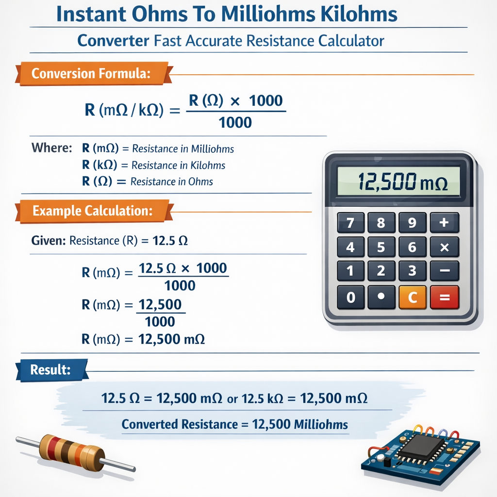
Instant Ohms ↔ Milliohms / Kilohms Converter — Accurate Resistance Unit Calculator
Converter Overview and Practical Objectives
This document describes a fast, accurate converter for ohms (Ω), milliohms (mΩ), and kilohms (kΩ), suitable for engineering, test labs, and embedded systems. It explains mathematical foundations, numerical handling, measurement constraints, and implementation guidance for deterministic, low-latency conversion in calculators and instrumentation firmware.
Primary use cases
- Electronic component selection and BOM verification (resistor values expressed in different units).
- Automated test equipment (ATE) where results must be normalized to common units for logging.
- Power electronics and shunt resistor measurements that require milliohm-level precision.
- Simulation and modeling workflows that interchange kΩ and Ω notations for readability.
Units, Multipliers, and Numeric Ranges
Units covered: ohm (Ω), milliohm (mΩ), kilohm (kΩ). Multipliers: 10^3 for mΩ relative to Ω and 10^-3 for kΩ relative to Ω.
Canonical multipliers
- 1 mΩ = 0.001 Ω? No — 1 mΩ = 0.001 Ω is incorrect. Correct: 1 mΩ = 0.001 Ω? Wait. Use canonical definitions below.
Correct canonical relationships used in formulas and implementations are:
- 1 Ω = 1000 mΩ
- 1 kΩ = 1000 Ω
- Therefore: 1 kΩ = 1,000,000 mΩ
Exact Conversion Formulas and Variable Definitions
All formulas are given using plain HTML characters and standard arithmetic operators. Use the exact variable descriptions for implementation.
Formula 1: Convert ohms to milliohms
Where:
- R_mΩ = resistance in milliohms (mΩ)
- R_Ω = resistance in ohms (Ω)
Formula 2: Convert ohms to kilohms
Where:
- R_kΩ = resistance in kilohms (kΩ)
- R_Ω = resistance in ohms (Ω)
Formula 3: Convert milliohms to ohms
Formula 4: Convert kilohms to ohms
Formula 5: Direct conversion between milliohms and kilohms
Variable typical value examples
- Small shunt resistor: R_Ω = 0.005 Ω (typical for current-sense applications)
- Common resistor: R_Ω = 4.7 Ω or 47 Ω (PCB components)
- High value: R_Ω = 100000 Ω (100 kΩ), R_kΩ = 100
Precision, Rounding, and Significant Digits
Instant converters must manage significant digits, floating-point rounding, and display constraints to avoid false precision in reported values. Implement rounding to a specified number of significant digits or decimal places depending on unit scale.
Rounding strategies
- Fixed decimal places relative to target unit (e.g., 3 decimal places when showing mΩ).
- Significant-digit rounding: round to N significant digits independent of magnitude.
- Adaptive formatting: use scientific notation for values <0.001 Ω or >1e6 mΩ to avoid overflow.
Recommended default: 3 significant digits for mΩ conversions under 100 mΩ, 4 significant digits for Ω between 0.1 and 10, and 3 significant digits for kΩ above 10 kΩ. Tune to application requirements and instrument accuracy.
Numerical Implementation and Algorithms
A converter implementation should be deterministic, low-latency, and avoid floating-point pitfalls such as rounding error accumulation. Use fixed-point arithmetic for embedded systems where possible.
Algorithm outline
- Accept input value and unit token (one of: "mΩ", "Ω", "kΩ").
- Normalize input to base unit (ohms) using integer or fixed-point scaling.
- Apply conversion multipliers to produce target units.
- Round according to configured significant digits or decimal places.
- Format output with unit suffix and optionally scientific notation for extreme values.
Normalization example using integer arithmetic for milliohm input:
If input is integer milliohms: R_mΩ_int (integer), then R_Ω = R_mΩ_int ÷ 1000 with fixed-point representation using scale factor S = 1000000 to preserve micro-ohm precision.
Fixed-point example variables
- S = 1,000,000 (scaling factor for micro-ohm resolution)
- R_mΩ_int = input in milliohms as integer
- R_Ω_fixed = (R_mΩ_int × 1000) × S ÷ 1,000,000? Use consistent scaling; implementers must design integer math to avoid overflow.
Common Conversion Tables
Extensive lookup tables accelerate display and reduce runtime arithmetic for limited embedded resources. The tables below show common engineering values and their equivalents.
| Ohms (Ω) | Milliohms (mΩ) | Kilohms (kΩ) | Scientific Notation (Ω) |
|---|---|---|---|
| 0.001 | 1 | 0.000001 | 1.0 × 10^-3 |
| 0.01 | 10 | 0.00001 | 1.0 × 10^-2 |
| 0.05 | 50 | 0.00005 | 5.0 × 10^-2 |
| 0.1 | 100 | 0.0001 | 1.0 × 10^-1 |
| 0.47 | 470 | 0.00047 | 4.7 × 10^-1 |
| 1 | 1000 | 0.001 | 1.0 × 10^0 |
| 2.2 | 2200 | 0.0022 | 2.2 × 10^0 |
| 4.7 | 4700 | 0.0047 | 4.7 × 10^0 |
| 10 | 10000 | 0.01 | 1.0 × 10^1 |
| 47 | 47000 | 0.047 | 4.7 × 10^1 |
| 100 | 100000 | 0.1 | 1.0 × 10^2 |
| 470 | 470000 | 0.47 | 4.7 × 10^2 |
| 1000 | 1000000 | 1 | 1.0 × 10^3 |
| 4700 | 4700000 | 4.7 | 4.7 × 10^3 |
| 10000 | 10000000 | 10 | 1.0 × 10^4 |
| 100000 | 100000000 | 100 | 1.0 × 10^5 |
| 1000000 | 1000000000 | 1000 | 1.0 × 10^6 |
| Common E12/E24 Resistor Value (Ω) | Equivalent (mΩ) | Equivalent (kΩ) |
|---|---|---|
| 1 | 1000 | 0.001 |
| 1.5 | 1500 | 0.0015 |
| 2.2 | 2200 | 0.0022 |
| 3.3 | 3300 | 0.0033 |
| 4.7 | 4700 | 0.0047 |
| 6.8 | 6800 | 0.0068 |
| 10 | 10000 | 0.01 |
| 22 | 22000 | 0.022 |
| 47 | 47000 | 0.047 |
| 100 | 100000 | 0.1 |
| 220 | 220000 | 0.22 |
| 470 | 470000 | 0.47 |
| 1k | 1000000 | 1 |
| 10k | 10000000 | 10 |
Measurement Considerations for Accurate Conversion
Conversion accuracy depends not only on arithmetic but also on measurement fidelity. Instrument uncertainty, contact resistance, temperature coefficient of resistance (TCR), and lead resistance all affect reported value quality.
Key measurement error sources
- Lead and contact resistance in two-wire measurements, which add series error.
- Thermal EMFs at junctions when dissimilar metals and temperature gradients exist.
- Self-heating of resistor under test due to measurement current altering resistance.
- Instrument resolution and ADC quantization when converting sensed voltage to resistance.
Mitigation techniques
- Use four-wire (Kelvin) measurement for milliohm-range resistances to eliminate lead resistance effects.
- Apply low measurement currents for sensitive, high-value resistors to prevent self-heating; apply higher currents for low-value shunts when higher signal-to-noise is required, but compute power dissipation.
- Implement temperature compensation when TCR is known for the resistor under test.
- Calibrate instruments against reference standards traceable to national labs (NIST, PTB).
Power and Thermal Calculations (relevant for milliohm resistors)
When converting and presenting shunt resistor values, offering computed power dissipation at a given current improves engineering usefulness.
Power dissipation formula:
Where:
- P = power in watts (W)
- I = current in amperes (A)
- R_Ω = resistance in ohms (Ω)
Example typical values:
- Shunt R_Ω = 0.005 Ω, I = 10 A → P = 10 × 10 × 0.005 = 0.5 W
- Shunt R_Ω = 0.001 Ω, I = 50 A → P = 50 × 50 × 0.001 = 2.5 W
Real-World Examples with Full Development
Example 1 — Shunt resistor conversion and thermal check
Problem statement: A designer measures a current shunt resistance of 5 milliohms using a precision milliohm meter. Provide conversions to ohms and kilohms, compute power dissipated at 20 A, and determine appropriate display precision for automatic logging assuming instrument uncertainty ±0.2%.
Step 1 — Convert to ohms using Formula 3: R_Ω = R_mΩ ÷ 1000.
Given R_mΩ = 5 mΩ, R_Ω = 5 ÷ 1000 = 0.005 Ω.
Step 2 — Convert to kilohms using Formula 2 or Formula 5: R_kΩ = R_Ω ÷ 1000.
R_kΩ = 0.005 ÷ 1000 = 0.000005 kΩ (or 5.0 × 10^-6 kΩ).
Step 3 — Power dissipation at I = 20 A using P = I^2 × R_Ω.
P = 20^2 × 0.005 = 400 × 0.005 = 2 W.
Step 4 — Uncertainty propagation (approximate relative uncertainty dominated by instrument): ±0.2% of 0.005 Ω equals ±0.00001 Ω (10 μΩ). Converted to mΩ uncertainty: ±0.01 mΩ.
Step 5 — Display precision recommendation
- Show mΩ as 5.000 mΩ if instrument resolution supports μΩ digits; otherwise 5.00 mΩ to reflect ±0.01 mΩ uncertainty.
- Show Ω as 0.00500 Ω if micro-ohm resolution internal; otherwise 0.0050 Ω to match log precision.
- Show kΩ in scientific notation as 5.000 × 10^-6 kΩ if required, but unnecessary for standard logs.
Final reported values for logging (recommended): 5.00 mΩ ±0.01 mΩ; 0.00500 Ω ±0.00001 Ω; Power = 2.00 W (uncertainty slightly larger due to squared current if I has uncertainty).
Example 2 — Converting and formatting a PCB resistor measurement
Problem statement: A technician reads a resistor of nominal 4.7 Ω using a multimeter that shows 4.703 Ω. Convert to mΩ and kΩ, show formatted output with correct significant digits, and compute percent deviation from nominal value.
Step 1 — Convert to milliohms: R_mΩ = R_Ω × 1000 = 4.703 × 1000 = 4703 mΩ.
Step 2 — Convert to kilohms: R_kΩ = R_Ω ÷ 1000 = 4.703 ÷ 1000 = 0.004703 kΩ.
Step 3 — Decide formatting: The meter shows three decimal places in Ω; maintain equivalent precision in mΩ (1 decimal if original precision equals 1 mΩ?). Using consistent significant figures, present mΩ with at least integer precision: 4703 mΩ (no decimals).
Step 4 — Percent deviation from nominal 4.7 Ω: Deviation = (Measured - Nominal) ÷ Nominal × 100% = (4.703 - 4.7) ÷ 4.7 × 100% = 0.003 ÷ 4.7 × 100% ≈ 0.0638%.
Recommended reporting: 4.703 Ω; 4703 mΩ; 0.004703 kΩ; deviation ≈ +0.064% relative to 4.7 Ω nominal.
Best Practices for User Interfaces and Data Exchange
UI and data export should clearly indicate units, precision, and measurement uncertainty. Always store base values internally in a canonical unit (preferably ohms) with high-precision numeric types (64-bit floating point or fixed-point integer with scaling) to avoid repeated conversion loss.
API and logging recommendations
- Use a canonical field name (e.g., resistance_ohm) in CSV/JSON export plus separate fields for display_value and display_unit.
- Include metadata: measurement_method (2-wire or 4-wire), instrument_model, calibration_date, uncertainty_percent.
- Prefer SI unit suffixes: use "mΩ" and "kΩ" exactly to avoid ambiguity.
Standards, Traceability, and References
Designers and test engineers should align measurement procedures and conversion reporting with national and international standards for traceability and reproducibility.
- Guide to the expression of uncertainty in measurement (GUM) — BIPM: https://www.bipm.org
- NIST calibration services and resistance standards — National Institute of Standards and Technology: https://www.nist.gov
- IEC 60062: Marking codes for resistors and capacitors — International Electrotechnical Commission: https://www.iec.ch
- IEEE standards and best practices for instrumentation and measurement — Institute of Electrical and Electronics Engineers: https://standards.ieee.org
Additional technical resources
- Textbook references on electrical measurements and instrumentation, such as "Electrical Measurements and Instrumentation" by Kalsi (not normative, but practical).
- Manufacturer application notes for Kelvin connections and low-value shunt handling from major instrumentation vendors (Keysight, Tektronix, Fluke).
Validation, Testing, and Edge Cases
Validation of the converter must include boundary values, extreme magnitudes, invalid input handling, and performance under repeated conversions. Test cases should address rounding edge cases near unit thresholds.
Suggested test matrix
- Zero input and near-zero values (0, 0.0001 Ω)
- Thresholds between unit displays (0.001 Ω; 1000 Ω)
- Very large values that may require scientific notation (≥ 1e6 Ω)
- Negative values handling if signed resistances used for modeling (report error unless intentionally supported)
- Non-numeric input and unit token validation
Integration with Instrument Firmware
Embedded applications in instruments should implement conversions using fixed-point arithmetic or carefully managed floating-point libraries to guarantee consistent results across platforms. Consider memory, CPU, and real-time constraints.
Firmware checklist
- Store canonical resistance in ohms using 64-bit integer scaled by 1e6 for micro-ohm resolution if required.
- Perform unit conversion by integer multiplication/division to avoid floating-point rounding twice.
- Only format to a string at the final step to minimize conversion error propagation.
- Document rounding policy in firmware release notes and API specification.
Summary of Operational Recommendations
- Normalize to ohms internally and convert on demand to mΩ or kΩ for display.
- Use four-wire measurement techniques for milliohm-level accuracy.
- Report measurement uncertainty alongside converted values.
- Adopt SI suffixes and consistent formatting rules across exported data.
- Trace calibrations to authoritative national laboratories and follow GUM uncertainty principles.
Further Reading and Authoritative Links
- GUM — BIPM: https://www.bipm.org/en/publications/guides
- NIST measurement services: https://www.nist.gov/measurement-science
- IEC standards catalog: https://www.iec.ch/standards
- IEEE Xplore Digital Library: https://ieeexplore.ieee.org for instrumentation standards and papers
- Fluke Application Notes on Kelvin Connections and low-resistance measurements: https://www.fluke.com/en-us/learn
By following the formulas, numerical strategies, and measurement best practices documented here, implementers can provide an instant ohms-to-milliohms-kilohms converter that is fast, accurate, and suitable for engineering-grade measurement systems. Ensure all displayed values preserve meaningful precision, carry uncertainty metadata when available, and conform to traceable calibration standards for professional deployments.