This article provides technical guidance for calculating conductor resistance for AWG and kcmil sizes accurately.
Copper and aluminum conductors require different resistivity values and temperature corrections for precise computations here.
Instant Electrical Conductor Resistance Calculator (AWG / kcmil, Cu / Al, Ω)
Fundamentals of electrical conductor resistance
Electrical conductor resistance depends on material resistivity, cross-sectional area, and conductor length. Practical calculations use circular mils for AWG and kcmil sizes.
Basic physical relation
The core relationship used in all later derivations is:
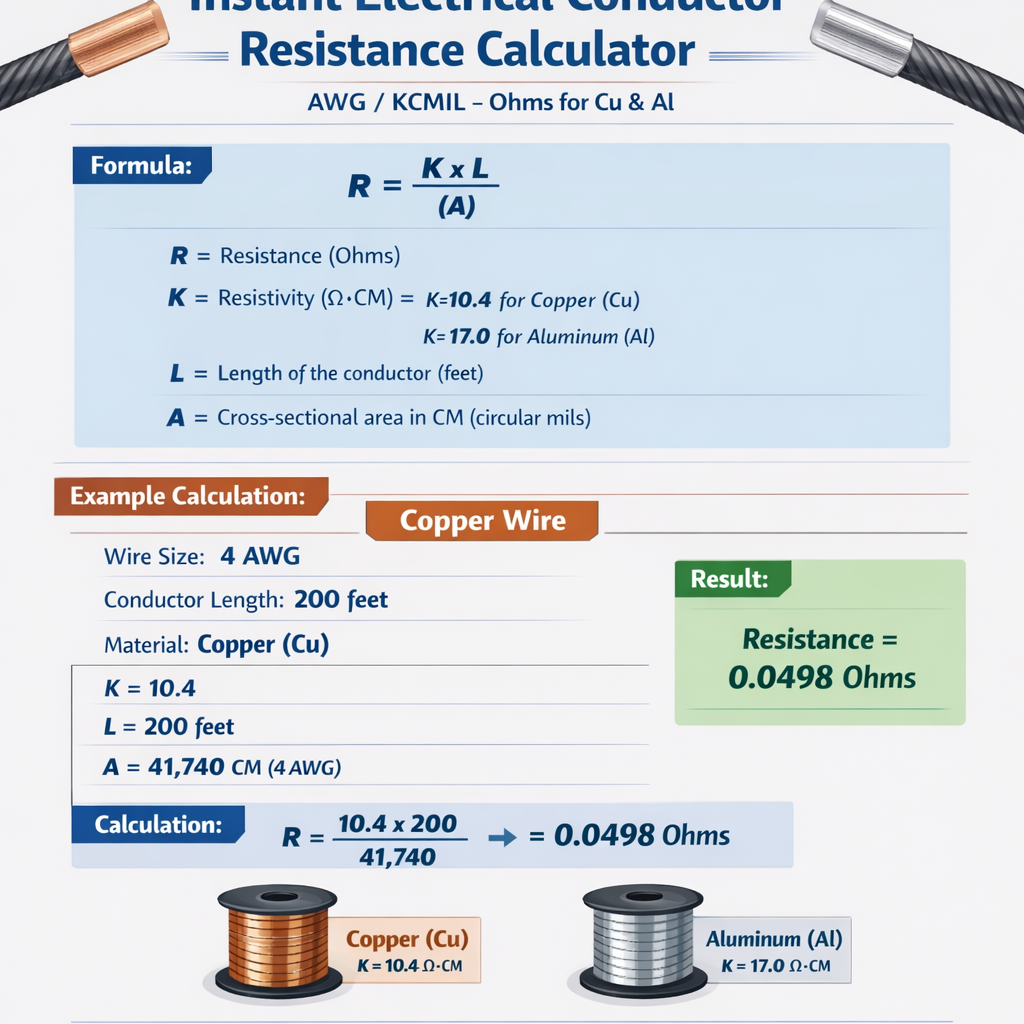
Where variables are:
- R = resistance (ohms)
- rho = material resistivity constant (ohm·mil/ft at reference temperature, typically 20 °C)
- L = conductor length (ft)
- A = conductor cross-sectional area (circular mils, cmil)
Standard resistivity constants and temperature coefficients
Industry practice uses useful constants expressed as ohm·mil/ft at 20 °C for convenience with AWG/kcmil units:
- Copper: rho_cu = 10.37 ohm·mil/ft (at 20 °C)
- Aluminum: rho_al = 17.24 ohm·mil/ft (at 20 °C)
Temperature affects resistance with an approximately linear coefficient near ambient:
Where:
- R_T = resistance at temperature T (°C)
- R_20 = resistance at 20 °C
- alpha = temperature coefficient (1/°C). Typical values:
- Copper: alpha_cu ≈ 0.00393 /°C
- Aluminum: alpha_al ≈ 0.0039 /°C
Formulas implemented by an instant resistance calculator
Resistance for a given length and conductor area
Using the resistivity constant the working formula becomes:
For convenience you often compute resistance normalized to 1000 ft:
Then R for arbitrary length L (ft) is:
Unit conversions commonly required
To convert R per 1000 ft to R per foot:
To convert to ohm per kilometer (ohm/km):
Because 1 ft = 0.3048 m and 1000 m = 1 km, multiply ohm/ft by 3280.8399 to get ohm/km.
Reference tables for common AWG and kcmil sizes
Tables below give circular mils, kcmil, copper and aluminum resistances per 1000 ft and per foot at 20 °C using the constants above.
| AWG / kcmil | Area (cmil) | Area (kcmil) | Cu R (ohm / 1000 ft) | Cu R (ohm / ft) | Al R (ohm / 1000 ft) | Al R (ohm / ft) |
|---|---|---|---|---|---|---|
| 14 | 4107 | 4.107 | 2.526 | 0.002526 | 4.197 | 0.004197 |
| 12 | 6530 | 6.530 | 1.588 | 0.001588 | 2.641 | 0.002641 |
| 10 | 10380 | 10.380 | 0.999 | 0.000999 | 1.661 | 0.001661 |
| 8 | 16510 | 16.510 | 0.6285 | 0.0006285 | 1.0449 | 0.0010449 |
| 6 | 26240 | 26.240 | 0.3954 | 0.0003954 | 0.6571 | 0.0006571 |
| 4 | 41740 | 41.740 | 0.2486 | 0.0002486 | 0.4129 | 0.0004129 |
| 2 | 66360 | 66.360 | 0.1563 | 0.0001563 | 0.2599 | 0.0002599 |
| 1 | 83690 | 83.690 | 0.1239 | 0.0001239 | 0.2061 | 0.0002061 |
| 1/0 | 105500 | 105.500 | 0.09835 | 0.00009835 | 0.1634 | 0.0001634 |
| 2/0 | 133100 | 133.100 | 0.07801 | 0.00007801 | 0.1296 | 0.0001296 |
| 3/0 | 167800 | 167.800 | 0.06185 | 0.00006185 | 0.1028 | 0.0001028 |
| 4/0 | 211600 | 211.600 | 0.04901 | 0.00004901 | 0.08147 | 0.00008147 |
Expanded kcmil selections used in utility and industrial distribution:
| kcmil | Area (cmil) | Cu R (ohm / 1000 ft) | Cu R (ohm / ft) | Al R (ohm / 1000 ft) | Al R (ohm / ft) |
|---|---|---|---|---|---|
| 250 | 250000 | 0.04148 | 0.00004148 | 0.06896 | 0.00006896 |
| 350 | 350000 | 0.02963 | 0.00002963 | 0.04926 | 0.00004926 |
| 400 | 400000 | 0.02593 | 0.00002593 | 0.04310 | 0.00004310 |
| 500 | 500000 | 0.02074 | 0.00002074 | 0.03448 | 0.00003448 |
| 750 | 750000 | 0.01383 | 0.00001383 | 0.02299 | 0.00002299 |
| 1000 | 1000000 | 0.01037 | 0.00001037 | 0.01724 | 0.00001724 |
Temperature correction and practical usage
Field calculations often require adjusting tabulated resistances from the reference 20 °C to the conductor operating temperature. Use the linear correction:
Example typical adjustments:
- At 75 °C, copper resistance increases roughly by 0.00393*(75-20) = 0.213 or about 21.3% above 20 °C.
- Aluminum at 75 °C increases by 0.0039*(75-20) = 0.2145 or about 21.45% above 20 °C.
When calculating voltage drop, losses, or fault currents, always use the operating temperature for correct conductor resistance.
Skin effect and AC considerations
For AC at power frequencies (50/60 Hz) and typical power conductor sizes, DC resistance approximations are acceptable for most low-frequency voltage-drop calculations. At higher frequencies or very large conductors, skin effect increases effective resistance. Key points:
- Skin effect becomes noticeable for very large conductors and high harmonic-rich waveforms.
- Use AC resistance correction factors (from standards or manufacturer data) when frequency or waveform requires.
Worked examples with step-by-step solution
Example 1 — Copper conductor resistance for branch circuit
Problem statement:
- Calculate the DC resistance of a 12 AWG copper conductor, length 150 ft (one-way), at 20 °C.
- Adjust the resistance to 75 °C operating temperature.
Given data and constants:
- 12 AWG area A = 6530 cmil
- rho_cu = 10.37 ohm·mil/ft at 20 °C
- alpha_cu = 0.00393 /°C
- L = 150 ft
Step 1 — resistance per 1000 ft at 20 °C:
Step 2 — resistance for 150 ft at 20 °C:
Step 3 — adjust to 75 °C:
Final answer:
- 12 AWG copper, 150 ft at 20 °C: 0.2382 ohm
- 12 AWG copper, 150 ft at 75 °C: approximately 0.2897 ohm
Example 2 — Aluminum service conductor resistance and voltage drop
Problem statement:
- Compute the resistance of a 750 kcmil aluminum conductor, length 500 ft one-way (service conductor), at 20 °C.
- Calculate voltage drop for a 3-phase, 480 V delta supply delivering 800 A, using reactance ignored (worst-case resistive drop).
Given data:
- Area A = 750000 cmil
- rho_al = 17.24 ohm·mil/ft at 20 °C
- L = 500 ft
- Line-to-line voltage V_LL = 480 V, 3-phase, current I = 800 A
Step 1 — R per 1000 ft at 20 °C:
Step 2 — R for 500 ft:
Step 3 — voltage drop in a 3-phase line using resistive formula:
Compute:
Step 4 — percent voltage drop relative to 480 V:
Final answers:
- 750 kcmil aluminum, 500 ft at 20 °C: R ≈ 0.01149 ohm (one-way)
- Resistive 3-phase voltage drop at 800 A: ≈ 15.92 V, which is ≈ 3.32% of 480 V
Calculator implementation notes, validation and edge cases
When implementing an instant resistance calculator for AWG and kcmil, consider the following:
- Input validation: require positive length, valid AWG/kcmil selection, and select material (Cu or Al).
- Unit handling: accept lengths in ft, m, km and properly convert; internal calculation easiest in ft and cmil.
- Temperature handling: allow user-specified conductor temperature and provide both reference (20 °C) and adjusted results.
- Precision: present results with appropriate significant digits—three or four decimals for small resistances.
- AC considerations: include an optional AC correction factor or callouts about skin and proximity effects at higher frequencies.
- Round-trip vs one-way: clearly state whether resistance returned is one-way or round-trip for voltage-drop calculations.
Validation against standards and manufacturers
Compare calculator outputs against published tables from authoritative sources (NEC, IEEE, manufacturer datasheets) to verify constants and rounding. Use reference resistivity constants and temperature coefficients documented by standards bodies where available.
Standards, normative references and authoritative resources
Key normative references and authoritative online resources for conductor resistance, AWG tables, and design rules:
- National Electrical Code (NEC) – National Fire Protection Association (NFPA). NEC tables and conductor ampacity guidance: https://www.nfpa.org/
- IEEE Standards (e.g., IEEE Std 80, IEEE Std 142) for grounding and conductor parameters: https://standards.ieee.org/
- IEC 60228 – Conductors of insulated cables; conductor cross-sectional area definitions: https://www.iec.ch/
- NIST material references and thermophysical properties for metals: https://www.nist.gov/
- Manufacturer datasheets (e.g., Southwire, Prysmian) for precise conductor construction and AC resistance corrections.
Practical tips for engineers and designers
- Always choose the conductor temperature consistent with the installation condition (ambient and loading). Using 20 °C for design only is insufficient where operating temperatures are higher.
- Prefer conservative rounding for protection calculations; use exact values for voltage-drop and efficiency calculations.
- For high-current, short-length fault calculations, use conductor DC resistance scaled to expected conductor temperature rise or use manufacturer fault tables.
- Keep units consistent in spreadsheet implementations: use cmil with rho in ohm·mil/ft, or convert to metric (mm² and ohm·m) but be consistent.
Quick workflow checklist for a calculation
- Select material (Cu or Al) and AWG/kcmil size.
- Lookup circular mil area (cmil).
- Compute R_1000ft = rho_constant * 1000 / A.
- Compute R for actual length L: R = R_1000ft * L / 1000.
- Apply temperature correction if needed: R_T = R * (1 + alpha * (T - 20)).
- Use R in downstream calculations (voltage drop, losses, fault currents).
Summary of key formulas and variable definitions
Primary calculator equations (text form):
- R = rho * L / A
- R_1000ft = rho * 1000 / A
- R_per_ft = R_1000ft / 1000
- R_T = R_20 * (1 + alpha * (T - 20))
- 3-phase resistive voltage drop: V_drop = sqrt(3) * I * R_oneway
Where typical constants are:
- rho_cu = 10.37 ohm·mil/ft at 20 °C
- rho_al = 17.24 ohm·mil/ft at 20 °C
- alpha_cu ≈ 0.00393 /°C
- alpha_al ≈ 0.0039 /°C
Additional reading and online tools
For verification and additional tables, consult published conductor tables in IEC or ANSI/IEEE resources and manufacturer catalogs. Online calculators (from reputable vendors or standards bodies) can be used to cross-check results but ensure they disclose the resistivity constants and temperature references they use.
References
- National Electrical Code (NEC), NFPA 70. https://www.nfpa.org/
- IEEE Standards Association. IEEE Std 141 (Red Book) and IEEE Std 142. https://standards.ieee.org/
- IEC 60228 — Conductors of insulated cables. https://www.iec.ch/
- NIST Reference on Physical Properties of Materials. https://www.nist.gov/
- Manufacturer conductor tables and datasheets (example: Southwire, Prysmian Group).