This article explains sizing equipment grounding conductor from overcurrent protective device rating per NEC 250.122.
Technical guidance, formulas, tables, and worked examples facilitate accurate instant EGC size calculations per code.
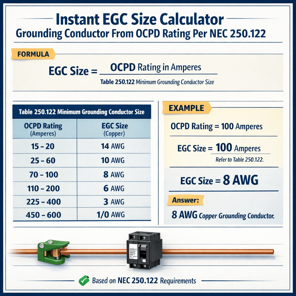
Instant EGC Size Calculator — Minimum Equipment Grounding Conductor (EGC) from OCPD Rating (per NEC 250.122)
Regulatory context and purpose of an instant EGC size calculator
NEC 250.122 sets the minimum equipment grounding conductor (EGC) sizes based on the rating of the overcurrent protective device (OCPD). An instant calculator maps an OCPD rating to the required EGC size so designers, installers, and inspectors can quickly confirm compliance with the code.
This article provides the normative basis, algorithmic approach, usable lookup tables, HTML formulas, worked examples, and authoritative references for practical deployment.
Key NEC references and authoritative sources
- NEC 250.122 — Equipment grounding conductor size relative to OCPD rating (primary normative reference).
- NEC 100, 110, 250 — Additional grounding, bonding, and conductor rules that can affect application and exceptions.
- NFPA: National Fire Protection Association, NEC publisher (https://www.nfpa.org).
- IAEI: International Association of Electrical Inspectors guidance and commentary (https://www.iaei.org).
- OSHA general electrical safety and grounding requirements (https://www.osha.gov).
Principles behind sizing the equipment grounding conductor
The EGC is sized to carry fault current until the OCPD clears; it does not need to carry continuous load current. NEC requires minimum sizes in Table 250.122 that correlate OCPD ampacity to a minimum EGC conductor size.
- EGC sizing is a table-lookup (NEC Table 250.122) driven by the OCPD rating.
- Material selection (copper or aluminum) changes the required AWG or kcmil size.
- Other rules can supersede the table: equipment-specific bonding jumpers, parallel conductors, terminals limitations, temperature/insulation ratings, and special installations.
Algorithm for an instant EGC size calculator
Inputs
- OCPD rating (A) — the rating of the overcurrent protective device protecting the circuit or feeder.
- Conductor material — typically copper (Cu) or aluminum (Al).
- Optional qualifiers — equipment bonding jumper, parallel grounding conductors, or manufacturer terminal limits.
Procedure (high level)
- Identify the controlling OCPD rating (in amperes).
- Reference the NEC Table 250.122 mapping for the applicable code edition.
- Select the minimum EGC size for the chosen material (Cu or Al).
- Apply exceptions or adjustments (bonding jumper tables, terminal lugs, parallel EGC rules).
- Document the selection and cross-reference the code table and any exceptions in the job record.
Lookup tables (common practical values)
Below are common, practical lookup values used in industry as a quick reference. These correlate typical OCPD ratings to minimum EGC sizes. Always verify against your jurisdiction’s adopted NEC edition and Table 250.122 for absolute compliance.
| OCPD Rating (A) | Minimum EGC (Copper AWG) | Minimum EGC (Aluminum AWG/kcmil) | Typical application (example) |
|---|---|---|---|
| 15 | #14 | #12 (Al commonly not used at 15A branch) | Small branch circuits (lighting, receptacle) |
| 20 | #14 | #12 | General purpose branch circuits |
| 30 | #10 | #8 | Small appliance circuits, water heater alternatives |
| 40 | #8 | #6 | Medium loads, small HVAC branch |
| 50 | #8 | #6 | Dishwashers, window units |
| 60 | #6 | #4 | Larger HVAC compressors, feeders |
| 100 | #4 | #2 | Service/feeder subpanels (typical 100A) |
| 150 | #3 | #1 | Large feeders or subservice conductors |
| 200 | #2 | 1/0 | Main service feeders |
| 400 | 1/0 | 3/0 | Large service or large feeders |
Note: This table is provided as a practical quick-reference. For precise, enforceable values consult the official NEC Table 250.122 in the adopted code edition for your jurisdiction.
HTML formulas and variable explanation for instant calculation
The EGC selection is effectively a table lookup; we show the logical formula in plain expression form that an instant calculator would implement. All variables are explained below.
Basic algorithmic expression (conceptual):
Where variables are:
- OCPD_rating — numeric rating in amperes (A) of the protective device protecting the circuit or feeder.
- material — conductor material: "Cu" = copper, "Al" = aluminum (or "Cu-clad Al" with caution).
- EGC_size — result returned as AWG or kcmil (string or numeric representation).
Expanded conditional form (example logic):
IF OCPD_rating <= 20 THEN EGC_size = (material == "Cu" ? "#14" : "#12")
ELSE IF OCPD_rating <= 30 THEN EGC_size = (material == "Cu" ? "#10" : "#8")
ELSE IF OCPD_rating <= 60 THEN EGC_size = (material == "Cu" ? "#6/#8 range" : "#4/#6 range")
ELSE EGC_size = TABLE_LOOKUP(OCPD_rating, material)
Typical values for variables in examples:
- OCPD_rating typical: 15, 20, 30, 60, 100, 200 (A)
- material typical: "Cu" or "Al"
- EGC_size typical outputs: "#14", "#10", "#6", "#4", "#2", "1/0"
Notes about the formulaic approach
- The actual NEC requirement is the table itself; a formula is only a way to automate the lookup.
- An instant calculator must enforce exact table entries for the NEC edition being used, not inferred scaling ratios.
- Ensure any UI allows the user to select the NEC edition and shows a clear citation to Table 250.122.
Worked example 1 — Branch circuit, 30 A OCPD (range hood)
Problem statement: Determine the minimum equipment grounding conductor size for a 30 A branch circuit protected by a 30 A breaker, using copper conductors.
Data and assumptions
- OCPD_rating = 30 A
- Material = Copper (Cu)
- Assume no special bonding jumper exceptions apply, and terminals accept the EGC selected per manufacturer data.
Step-by-step calculation (lookup)
- Identify OCPD rating: 30 A.
- Consult NEC Table 250.122 (instant calculator performs lookup).
- From the practical lookup table above, for 30 A, minimum EGC (Cu) = #10 AWG.
Result and justification
Minimum EGC size = #10 copper.
Rationale: Table 250.122 maps a 30 A OCPD to a #10 Cu EGC minimum. Ensure the selected conductor and terminal accept the EGC and that terminations conform with the manufacturer and 110.14(C) type requirements.
Worked example 2 — Service/feeder, 200 A OCPD (main service)
Problem statement: For a 200 A main service OCPD feeding a residential service disconnect, determine the minimum EGC size, using copper conductors for the grounding conductor to the subpanel bonding point.
Data and assumptions
- OCPD_rating = 200 A
- Material = Copper (Cu)
- Application: equipment grounding conductor sizing for feeder/main that will be connected to service equipment or a large subpanel.
- Assume the locally adopted NEC edition maps 200 A to a typical EGC size per Table 250.122.
Step-by-step calculation (lookup)
- Identify OCPD rating: 200 A.
- Consult NEC Table 250.122. For a 200 A OCPD, common practice mapping requires a #2 copper EGC minimum for service/main feeders.
- Select EGC = #2 Cu (and verify terminal lug ratings accept #2).
Result and justification
Minimum EGC size = #2 copper.
Rationale: For high-amperage service equipment, Table 250.122 requires significantly larger grounding conductors to safely carry fault current until the main OCPD clears. Confirm the final selection against the exact adopted NEC table or local amendment.
Worked example 3 — Additional real-world case: Aluminum EGC for 60 A OCPD
Problem statement: Determine the minimum aluminum equipment grounding conductor for a 60 A OCPD protecting an outdoor subpanel feeder, with conductors in conduit.
Data and assumptions
- OCPD_rating = 60 A
- Material = Aluminum (Al) — typically use AWG or kcmil per Table 250.122
- Assume acceptable terminations for aluminum and anti-oxidant compound where needed.
Procedure
- Lookup 60 A on Table 250.122 for aluminum conductors.
- From practical lookup, 60 A → minimum EGC (Al) = #4 AWG (some practices use #4 Al; verify table in edition).
- Confirm that conduit fill, connector ratings, and local rules permit aluminum EGC for the connection point.
Result
Minimum EGC size = #4 aluminum (verify with the adopted NEC table and manufacturer terminal sizes).
Practical considerations and exceptions
Equipment bonding jumpers and special cases
- NEC contains provisions where a specific equipment bonding jumper is sized differently than the Table 250.122 due to short-circuit current or equipment manufacturer requirements. Always review 250.122 exceptions and 250.32(C), 250.66, and 250.122 notes.
- For certain motor circuits, appliances, or separately derived systems, sizing can be influenced by other NEC sections.
Terminal ratings and conductor termination
- Always verify that the selected EGC size is acceptable for the terminal or lug with which it will be terminated. Manufacturer terminal ratings may limit AWG sizes.
- If the terminal cannot accept the NEC-mandated minimum size, follow NEC 110.14(C) for listed and marked terminals or provide an approved adapter/connector.
Parallel grounding conductors
- NEC permits parallel equipment grounding conductors under limited conditions. When installing parallel EGCs, each conductor must be sized and terminated per 250.122 and 250.4(B).
- Coordinate multiple EGCs so the effective cross-section equals or exceeds the required single conductor size, and ensure connection integrity at both ends.
Temperature, insulation, and derating
- EGCs are not required to carry continuous load but must be compatible with the environment (temperature, humidity) and the termination hardware.
- Select insulation type and temperature rating that match the installation conditions and the connectors’ ratings.
Designing an instant calculator UI and validation logic
Key UI elements and validation rules for a compliant instant EGC Size Calculator:
- Input fields: OCPD rating (numeric), material selector (Cu/Al), NEC edition selector (2014/2017/2020/2023, etc.), and optional context modifiers (bonding jumper, parallel conductors).
- Validation: ensure OCPD rating is a positive integer and valid common values; flag uncommon values for manual review.
- Output: show selected EGC size, cite the exact Table 250.122 row, include code reference (NEC 250.122), and show any applicable exceptions or terminal considerations.
- Audit trail: record inputs, selected NEC edition, timestamp, and a statement to “verify with AHJ and manufacturer” before installation.
Testing and verification for field use
Before using the calculator in production or as a compliance tool, perform the following tests:
- Cross-check calculator outputs against the official NEC Table 250.122 for multiple OCPD values and both materials.
- Simulate edge cases: non-standard OCPD ratings, parallel EGCs, and binding terminal size conflicts.
- Field test with electricians and inspectors; collect feedback regarding usability and clarify any ambiguous wording.
- Implement an update mechanism so the calculator can switch to newer code editions and table changes as authorities adopt new NEC versions.
Common pitfalls and mitigation
- Mistake: Using conductor ampacity tables to size the EGC. Mitigation: Use Table 250.122; EGC is table-driven, not ampacity-driven.
- Mistake: Ignoring material differences. Mitigation: Always set material input and map to the correct table entries for Cu vs. Al.
- Mistake: Not checking terminal lug size. Mitigation: Cross-check manufacturer terminal allowable conductor sizes and provide alternate solutions in the app output.
- Mistake: Assuming continuous loads influence EGC size. Mitigation: EGC sizing is for fault current, not continuous load carrying—do not apply ampacity derating logic to EGC sizing except where explicitly required by NEC sections.
Maintenance of the calculator and code updates
NEC editions are periodically updated; Table 250.122 may receive edits or clarifications. Maintain a single authoritative data source for table mappings and track adoption dates by jurisdiction. Include a version/display of the NEC edition used for each calculation result.
References and further reading
- NFPA 70, National Electrical Code — official edition and Table 250.122 (refer to the edition adopted by your jurisdiction). See NFPA: https://www.nfpa.org
- NEC Handbook commentary on Article 250 — consult for explanatory guidance and examples (publisher: NFPA).
- IAEI — technical articles and commentary on grounding and bonding practice: https://www.iaei.org
- OSHA electrical standards and grounding guidance (general safety and enforcement context): https://www.osha.gov
- Manufacturer terminal and lug datasheets — for termination compatibility (vendor websites and product datasheets).
Summary of best practices for instant EGC calculators
- Implement exact lookup values from the NEC Table 250.122 for the chosen code edition; do not approximate with scaling rules.
- Always include the NEC edition, table citation, and an advisory to verify with the Authority Having Jurisdiction (AHJ).
- Provide clear UI fields for material, OCPD rating, and installation qualifiers (parallel conductors, specific equipment).
- Log calculations and inputs for traceability and inspection records.
Appendix: Additional common lookup table (expanded)
The table below expands common OCPD ratings and the frequent minimum EGC sizes used by practicing electricians. This is an expanded practical quick-reference; final compliance requires checking the NEC table used in your area.
| OCPD (A) | Cu EGC (AWG) | Al EGC (AWG / kcmil) | Notes |
|---|---|---|---|
| 15 | #14 | #12 | Small lighting/receptacle circuits |
| 20 | #14 | #12 | General-purpose branch circuits |
| 25 | #12 | #10 | Some unusual small OCPDs |
| 30 | #10 | #8 | Common branch circuits: water heaters, etc. |
| 40 | #8 | #6 | Medium-sized loads |
| 50 | #8 | #6 | Common for small appliance circuits |
| 60 | #6 | #4 | Larger HVAC and feeders |
| 70 | #6 | #4 | Nonstandard; verify with table |
| 80 | #4 | #2 | Feeder and service-related circuits |
| 100 | #4 | #2 | Common 100 A feeder |
| 150 | #3 | #1 | Large feeders — verify manufacturer lug |
| 200 | #2 | 1/0 | Main services and large feeders |
| 400 | 1/0 | 3/0 | Large service equipment |
Reminder: The exact AWG/kcmil mapping should be confirmed against the adopted NEC edition. This appendix is intended to illustrate typical practice and to support an instant calculator’s test vectors.
Implementation checklist for field engineers
- Confirm the NEC edition adopted in the project jurisdiction.
- Identify the exact OCPD rating and conductor material.
- Run the instant calculator and capture the table reference (NEC 250.122).
- Verify terminal/lug acceptance of the selected EGC size.
- Document selection in the job record and present during inspection.
Final compliance note
NEC Table 250.122 is the definitive source for minimum EGC sizes. This article provides an implementation and practical references to support an instant EGC size calculator, example calculations, and design guidance. Always verify values against the official code edition and consult the AHJ for any local amendments or interpretations.