Instant conduit sizing reduces installation errors and ensures compliance with NEC conductor fill limits accurately.
This article provides calculators, formulas, tables, examples, and code references for professional electrical design engineers.
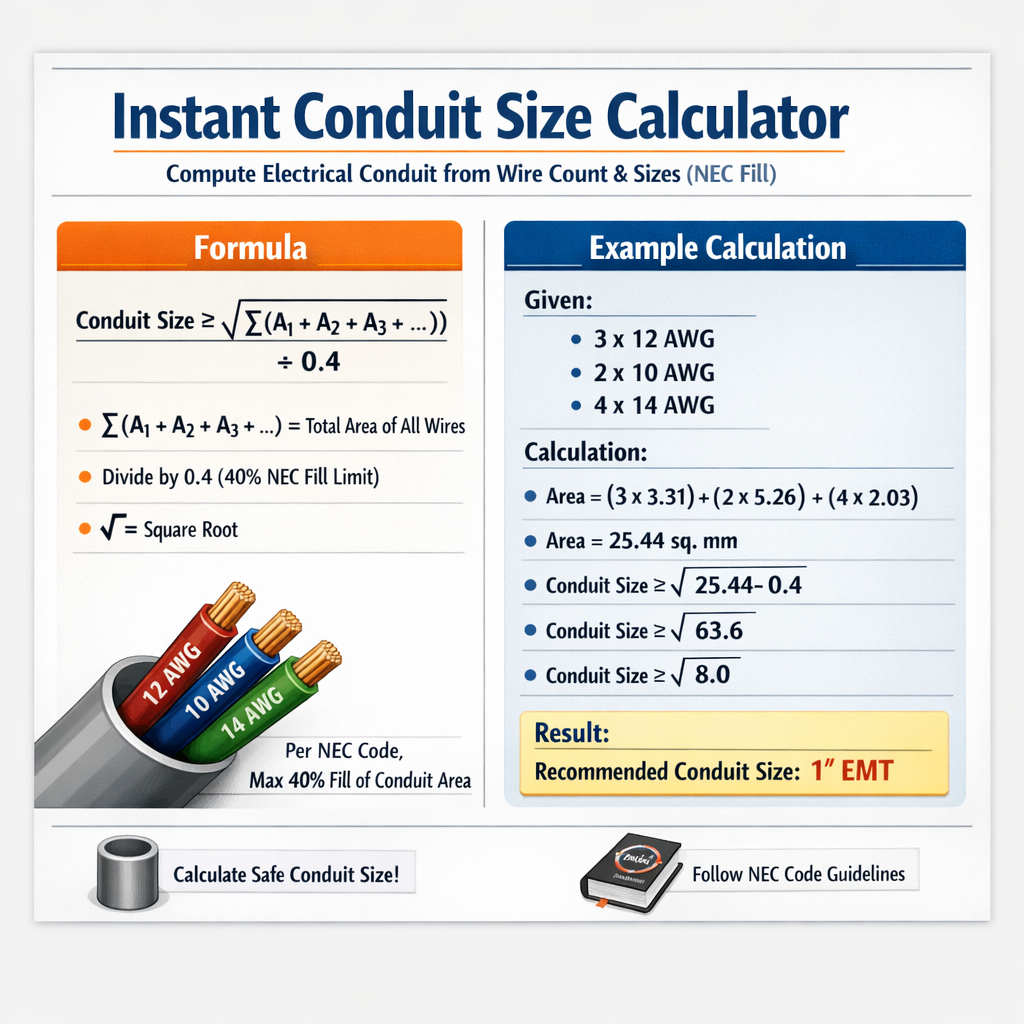
Instant Conduit Size Calculator — compute NEC conduit minimum from conductor count and insulated conductor diameter
Scope and purpose of the Instant Conduit Size Calculator
This document describes the theoretical basis, formulas, and worked examples used to compute conduit size from wire count and conductor sizes according to NEC fill rules. It targets electrical engineers, designers, and technicians who require a deterministic, auditable method to determine minimum conduit internal area and trade size for common installations.
Fundamental principles and NEC fill rules
The National Electrical Code (NEC) defines conduit fill limits to preserve conductor cooling, allow installation, and reduce mechanical damage. The governing rules are in NEC Chapter 9, Note 1 and related tables. The usual rule set used for conduit sizing:
- One conductor in a raceway: maximum fill = 53% of the conduit internal cross-sectional area.
- Two conductors in a raceway: maximum fill = 31% of the conduit internal cross-sectional area.
- More than two conductors in a raceway: maximum fill = 40% of the conduit internal cross-sectional area.
These percentages are applied to the sum of the cross-sectional areas of the insulated conductors. For cables or multicore conductors, NEC uses the cable overall area instead of individual insulated conductor areas.
Key formulas and variable definitions
All formulas below are presented using plain HTML expressions. Each formula is followed by variable definitions and typical values used in calculations.
1) Conductor cross-sectional area from circular mils
- Area_in_inch2: insulated conductor area, square inches (in²).
- CMI: circular mils of the conductor (typical values listed in tables below).
- 7.85398163397448e-7: conversion factor from circular mils to square inches (π/4 × (0.001 in)^2).
Typical value example: 12 AWG (CMI ≈ 6530) → Area_in_inch2 = 6530 × 7.85398e-7 ≈ 0.00513 in².
2) Conductor cross-sectional area from diameter
- Area: circular area of insulated conductor (in² or mm² depending on D units).
- D: insulated conductor outer diameter (same length units as desired area).
- π: mathematical constant ≈ 3.14159265358979.
Units: if D is in inches, Area is in square inches. If D is in millimetres, Area is in mm².
3) Total conductor area and conduit fill percentage
- TotalArea: sum of areas of insulated conductors or cables inside the conduit.
- ConduitInternalArea: internal cross-sectional area of the conduit (from manufacturer data or NEC Chapter 9 Table 4).
- FillPercent: percent fill used to verify against NEC allowable percentages (53%, 31%, 40%).
4) Required conduit internal area from conductor areas and allowable fill
- AllowedFillFraction: 0.53, 0.31, or 0.40 depending on number of conductors.
- Round up to the next standard conduit internal area for a trade size.
Common conductor areas and conversions (AWG and kcmil)
Use the following table to obtain circular mils (CMI) and convert to square millimetres and square inches for common AWG sizes. Values for CMI are standard, and conversion to mm² uses factor 0.0005067075 mm² per circular mil (1 cmil = 5.067075e-4 mm²). Conversion to square inches uses factor 7.8539816e-7 in² per circular mil.
| AWG | CMI (approx) | Area (mm²) ≈ | Area (in²) ≈ |
|---|---|---|---|
| 14 | 4107 | 2.08 | 0.00323 |
| 12 | 6530 | 3.31 | 0.00513 |
| 10 | 10380 | 5.26 | 0.00816 |
| 8 | 16510 | 8.37 | 0.01296 |
| 6 | 26240 | 13.29 | 0.02061 |
| 4 | 41740 | 21.16 | 0.03278 |
| 3 | 52620 | 26.67 | 0.04135 |
| 2 | 66360 | 33.64 | 0.05212 |
| 1 | 83690 | 42.40 | 0.06575 |
| 1/0 | 105600 | 53.56 | 0.08295 |
| 2/0 | 133100 | 67.42 | 0.10457 |
| 3/0 | 167800 | 85.03 | 0.13178 |
| 4/0 | 211600 | 107.21 | 0.16648 |
Note: Table values for mm² were computed with factor 0.0005067075 mm² per circular mil; values are rounded to two decimal places for clarity.
Typical conduit internal areas (selection of trade sizes)
Use manufacturer data or NEC Chapter 9 Table 4 for accurate internal areas. The table below lists common values for EMT and Schedule 40 PVC (approximate internal cross-sectional area). Verify against the specific conduit standard and manufacturer datasheets for precise installation and for larger trade sizes.
| Trade Size | EMT Internal Area (in²) | EMT Internal Area (mm²) | Schedule 40 PVC Internal Area (in²) | Schedule 40 PVC Area (mm²) |
|---|---|---|---|---|
| 1/2" | 0.304 | 196 | 0.304 | 196 |
| 3/4" | 0.533 | 344 | 0.533 | 344 |
| 1" | 0.864 | 557 | 0.864 | 557 |
| 1-1/4" | 1.496 | 965 | 1.496 | 965 |
| 1-1/2" | 2.036 | 1314 | 2.036 | 1314 |
| 2" | 3.356 | 2163 | 3.356 | 2163 |
| 2-1/2" | 4.914 | 3169 | 4.914 | 3169 |
| 3" | 7.069 | 4561 | 7.069 | 4561 |
| 4" | 11.67 | 7530 | 11.67 | 7530 |
Note: Values are representative; always use the exact conduit internal area supplied in the current NEC Chapter 9 tables or manufacturer documentation for final compliance checks.
Step-by-step method to compute conduit size from wire count and sizes
- Identify each conductor’s cross-sectional area (use circular mils table or measured insulated conductor diameter).
- Compute each insulated conductor area in consistent units (in² or mm²) using formula: Area = π × (D/2)² or Area = CMI × 7.8539816e-7 (for in²).
- Sum all conductor areas: TotalArea = Σ Area_i.
- Choose NEC allowed fill fraction using number of conductors (1 → 0.53; 2 → 0.31; >2 → 0.40).
- Compute RequiredConduitArea = TotalArea / AllowedFillFraction.
- Select the smallest standard conduit trade size whose internal area ≥ RequiredConduitArea.
- Document manufacturer table reference and NEC table used for legal traceability.
Worked example 1 — Motor feeder: three insulated phase conductors and equipment ground
Problem: Determine minimum conduit trade size for three 8 AWG THHN phase conductors and one 10 AWG THHN equipment grounding conductor. Use NEC more-than-two conductors rule (40% fill).
Data and assumptions
- Phase conductors: 3 × 8 AWG, CMI = 16510 each.
- Equipment ground: 1 × 10 AWG, CMI = 10380.
- Assume insulated conductor area uses circular mils conversion to in².
- Allowed fill fraction for more than two conductors: 0.40 (40%).
- Use EMT internal areas from the conduit table above for final selection.
Calculation
Step 1: Compute individual areas in in² using Area = CMI × 7.8539816e-7.
Step 4: Select conduit trade size where internal area ≥ 0.1176 in². From table:
- 1/2" EMT internal area = 0.304 in² (≥ 0.1176)
Result: Minimum conduit = 1/2" EMT. Fill = (0.04704 / 0.304) × 100% = 15.47% (well under allowed 40%).
Worked example 2 — Lighting branch: multiple 12 AWG conductors
Problem: Calculate conduit trade size for a lighting run containing 10 insulated 12 AWG THHN conductors (e.g., multiple switches and neutrals in a conduit). Use NEC more-than-two conductors rule (40% fill).
Data and assumptions
- 12 AWG CMI = 6530 per conductor.
- Insulated conductor area conversions use Area = CMI × 7.8539816e-7 in².
- Allowed fill fraction for more than two conductors = 0.40.
Calculation
Select conduit size:
- 1/2" EMT area = 0.304 in² (≥ 0.12825)
Result: Minimum conduit = 1/2" EMT. Fill percentage = (0.0513 / 0.304) × 100% = 16.87%.
Discussion of examples
Both examples illustrate that typical small conductor counts fit easily into 1/2" EMT. However, real projects often require additional conductors (controls, spare conductors, larger grounds), derating considerations for current-carrying capacity, and mechanical pulling considerations. Therefore, engineers often increase conduit size for future capacity and easier installation.
Advanced considerations for practical installations
- Insulation type: THHN/THWN, XHHW, or other insulation affects the insulated conductor diameter used to compute area—use manufacturer datasheets or NEC Chapter 9 Table 5 for precise insulated conductor areas.
- Bundled conductors and ampacity derating: NEC 310.15(B)(3)(a) requires ampacity derating when more than three current-carrying conductors are grouped—this is separate from conduit fill calculation but impacts conductor size and therefore conduit size indirectly.
- Conduit bends, pulling tension, and installation method: allow additional slack or increase trade size to reduce pulling friction and to accommodate pulling grips and splices.
- Spare conductors and future expansion: include allowance for one or more spare conductors or plan for larger conduit to avoid rework.
- Use cable assemblies instead of individual conductors: for cables, use the cable overall area from manufacturer; apply NEC fill percentages to the cable area per conduit.
Algorithmic checklist for an Instant Conduit Size Calculator
- Input: list of conductors (AWG or kcmil), insulation type (THHN/THWN/XHHW), or explicit insulated conductor diameter values.
- Map AWG/kcmil to CMI and calculate insulated conductor area (or take manufacturer area directly).
- Sum all areas and choose the appropriate NEC allowed fill fraction.
- Compute RequiredConduitArea = TotalArea / AllowedFillFraction.
- Look up conduit table to find the smallest trade size where internal area ≥ RequiredConduitArea.
- Output: trade size, conduit internal area, fill percentage, notes on ampacity derating and pulling difficulty.
Implementation notes for software calculators
- Precision: perform calculations in double precision and present results with at least three significant figures; round trade size selection conservatively.
- Data sources: embed or reference NEC Chapter 9 tables, manufacturer catalogs for conduit internal areas and insulated conductor diameters, and an AWG-to-CMI lookup table.
- User interface: allow both conductor count entry and cable area entry. Provide suggestions for spare conductors and show derivative effects on ampacity derating.
- Validation: include sanity-check warnings when computed fill is near NEC maximums (e.g., > 80% of allowed fill) or when the number of conductors triggers ampacity derating rules.
Regulatory references and authoritative resources
Relevant codes and standards for conduit fill and conductor sizing include:
- NFPA 70: National Electrical Code (NEC), Chapter 9, Tables 1–10 (conduit fill, conductor areas). Official site: https://www.nfpa.org/nec
- NEC Handbook or local adoption amendments for verifying the edition (e.g., NFPA 70 — 2020). Refer to the edition adopted by the local authority having jurisdiction (AHJ).
- IEC 60228: Conductors of insulated cables (for international conductor cross-section standards): https://www.iec.ch
- NEMA and manufacturer datasheets for specific conduit types (EMT, IMC, RMC, PVC) and internal areas: e.g., https://www.nema.org
- UL standards for wire and cable types (UL listed insulation types such as THHN/THWN): https://www.ul.com
Practical tips and common pitfalls
- Always verify current NEC edition in force locally; jurisdictional amendments may alter allowable practices.
- Do not substitute bare conductor circular mils for insulated conductor area unless insulation thickness is negligible; use table values for insulated conductors.
- When in doubt, select the next larger conduit trade size to account for pulling difficulties and future changes—document the rationale.
- Use conservative rounding: when RequiredConduitArea equals an available conduit internal area within rounding error, select the larger trade size.
- Document all assumptions: AWG sizes, insulation type, conversion factors, NEC tables used, and manufacturer sources for traceability.
Appendix: Conversion constants and quick formula cheatsheet
| Description | Formula / Constant | Notes |
|---|---|---|
| CMI → in² | Area_in_in² = CMI × 7.8539816e-7 | 1 circular mil = π/4 × (0.001 in)² ≈ 7.8539816e-7 in² |
| CMI → mm² | Area_mm² = CMI × 0.0005067075 | 1 circular mil ≈ 5.067075e-4 mm² |
| Circle area | Area = π × (D / 2)² | D units determine area units (inches → in²; mm → mm²) |
| Fill percent | Fill% = (TotalArea / ConduitArea) × 100 | Compare to NEC limits: 53%, 31%, 40% |
| Required conduit area | ReqArea = TotalArea / AllowedFillFraction | Pick smallest conduit with area ≥ ReqArea |
Final compliance and documentation checklist
- List all conductors (type, AWG, insulation) and any cables entering the conduit.
- Specify calculations showing each conductor area, total area, allowed fill fraction, and computed required conduit area.
- Reference NEC tables and manufacturer conduit internal area source (include edition/year).
- Record selected conduit trade size, expected fill percentage, and rationale for any upsizing for pull or spares.
- Include ampacity derating effects if applicable and verify overcurrent protection coordination when conductor sizes change.
Using the formulas and tables provided above, an Instant Conduit Size Calculator can deterministically compute conduit requirements from wire counts and sizes while ensuring NEC fill compliance. For ultimate accuracy, integrate manufacturer-specific insulated conductor dimensions and conduit internal areas, and reference the exact NEC edition adopted by the project’s authority having jurisdiction.
Useful external links for additional verification
- NFPA — National Fire Protection Association, NEC resources: https://www.nfpa.org/nec
- International Electrotechnical Commission (IEC): https://www.iec.ch
- NEMA — conduit and cable product standards: https://www.nema.org
- Underwriters Laboratories (UL) product directory: https://www.ul.com
- NEC commentary and handbook resources from recognized publishers and electrical engineering associations (search for NFPA 70 Handbook relevant edition)