This article provides a technical tool to select fuses aligned with NEC and international standards.
It describes calculation methods, examples, tables, and normative references for accurate fuse selection and verification.
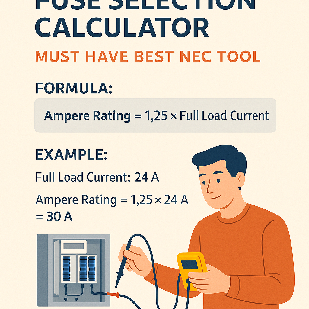
Fuse Selection Calculator — NEC-oriented Technical Tool
Technical framework for fuse selection and NEC alignment
Selecting the correct fuse requires understanding electrical load characteristics, overcurrent device behavior, conductor ampacity, and applicable codes. This section summarizes the essential technical and regulatory constraints that must drive any calculator or workflow used for fuse selection consistent with the NEC (National Electrical Code) and international standards such as IEC 60269.Key regulatory and technical drivers:- Continuous vs non-continuous loads: continuous loads commonly require the overcurrent protective device (OCPD) to be sized at 125% of the continuous current per standard practice under NEC rules for branch-circuit sizing.
- Motor circuits and special equipment: NEC Article 430 contains requirements for motor overcurrent protection; motors and transformers often use different selection multipliers or device types (time-delay fuses, inverse-time breakers).
- Interrupting rating: the selected fuse must have an interrupting rating greater than or equal to the available prospective short-circuit current at the installation point.
- Coordination and selectivity: discrimination between upstream and downstream devices requires time-current curve matching or selective fault-clearing strategies.
- Ambient temperature, conductor bundling, and correction factors: apply derating multipliers to fuse and conductor ratings when environmental or installation conditions differ from standard tables.
Fuse types, characteristics, and selection priorities
Understanding fuse construction and time-current behavior is crucial for automated selection. Fuse types relevant for NEC-compliant selection tools include:- Fast-acting (or general-purpose) fuses — minimal time-delay, useful for non-motor resistive loads.
- Time-delay / slow-blow fuses — allow inrush currents (motors, transformers) while protecting against sustained overloads.
- Current-limiting high-interrupting fuses — rapidly interrupt fault currents, reducing let-through energy (I²t).
- Semiconductor fuses — designed to protect power electronic devices with very low let-through energy.
- Dual-element fuses — combine overload tolerance and short-circuit protection, commonly used on motor circuits.
- Match fuse type to load behavior (inrush, overload, thermal sensitivity).
- Compute continuous-load multiplier and apply 125% rule when required.
- Verify conductor ampacity against fuse rating and apply temperature/derating corrections.
- Check available short-circuit current vs fuse interrupting rating (kA RMS symmetrical).
- Consider coordination with upstream devices for selective fault clearing.
Essential formulas and variable explanations
Below are the key formulas an NEC-aware fuse selection calculator must implement. Formulas are presented in plain HTML and each variable is explained with typical values.Single-phase current from real power: I_load = P / (V × PF)- I_load — load current in amperes (A).
- P — real power in watts (W). Typical values depend on load: resistive heaters (100–20,000 W), HVAC compressors (several kW to hundreds of kW).
- V — line-to-line voltage for single-phase (120 V or 240 V typical in North America, 230 V typical internationally).
- PF — power factor (dimensionless). Typical PF: motors 0.8–0.95, resistive loads 1.0, electronic loads 0.6–0.99.
- sqrt(3) ≈ 1.732.
- V — line-to-line voltage (e.g., 480 V, 400 V, 380 V commonly used).
- 1.25 — continuous load multiplier (typical NEC practice; verify for specific Article requirements).
- Choose closest higher standard fuse rating available commercially.
- Ampacity_required — conductor ampacity from NEC tables at the applicable temperature rating.
- Correction_factor — product of ambient temperature and grouping correction factors per NEC 310.15(B)(2)(a) (typical values less than or equal to 1.0).
- I — prospective fault current magnitude during fuse clearing.
- t — clearing time for the fuse given fault current (read from fuse time-current curves).
- Lower I²t implies less thermal and mechanical stress on protected components.
Tables of common fuse ratings and conductor pairings
Below are extensive tables of typical fuse ratings with commonly selected conductor cross-sections. These tables are for engineering reference and must be validated against the NEC, local amendments, and conductor insulation temperature ratings. Values shown are typical and rounded for practical selection.| Common Fuse Rating (A) | Typical Copper Conductor AWG/Size | Typical mm² Conductor | Typical Use Cases |
|---|---|---|---|
| 8 A | 18 AWG | 0.75 mm² | Lighting circuits, small control devices |
| 10 A | 16 AWG | 1.0 mm² | Control circuits, small heaters |
| 15 A | 14 AWG | 2.5 mm² | Branch circuits, lighting |
| 20 A | 12 AWG | 2.5–4.0 mm² | General-purpose circuits |
| 30 A | 10 AWG | 4.0–6.0 mm² | Small motors, appliances |
| 40 A | 8 AWG | 6.0–10 mm² | Large appliances, small distribution feeders |
| 60 A | 6 AWG | 16 mm² | Service feeders, large appliances |
| 100 A | 3 AWG | 25–35 mm² | Subpanels, motors |
| 150 A | 1/0 AWG | 50 mm² | Main feeders |
| 200 A | 2/0 AWG | 70 mm² | Main service, large feeders |
| 400 A | 350 kcmil | 185–240 mm² | Large distribution feeders |
| Fuse Type | Characteristic | Recommended Application | Typical Interrupting Rating |
|---|---|---|---|
| Fast-acting | Rapid clearing at small overloads | Resistive loads | 10 kA – 200 kA |
| Time-delay (dual-element) | High inrush tolerance, lower fusing for overloads | Motor starters, transformers | 10 kA – 200 kA |
| Current-limiting | Rapid fault clearing with reduced let-through | Distribution main protection | Up to 200 kA+ |
| Semiconductor (gR) | Very low I²t for electronic devices | Inverters, rectifiers | 10 kA – 200 kA |
Ambient temperature and derating rules — implementation details
A proper calculator must apply ambient temperature derating and conductor bundling corrections before finalizing fuse and conductor choices.Key steps:- Determine conductor insulation temperature rating (e.g., 75°C column for THHN on terminations rated 75°C).
- Look up base ampacity from NEC tables for the conductor size and temperature column.
- Apply ambient temperature correction factor per NEC table (e.g., at 30°C, 35°C, 40°C, etc.).
- Apply grouping/multi-conductor correction factors if more than three current-carrying conductors are in the same raceway or cable per 310.15(B)(3)(a).
- Ensure adjusted ampacity ≥ required ampacity (e.g., I_fuse_nominal / correction factors).
- Ambient correction factor for 30°C–35°C ≈ 0.91–0.94 depending on insulation; for higher temperatures factors reduce further.
- Grouping correction for 4–6 conductors ≈ 80–70% depending on table values.
Coordination, selective protection, and time-current analysis
Selective coordination ensures only the device closest to a fault clears that fault, maintaining upstream power continuity. A calculator should:- Compute time-current curves (or use manufacturer TCC data) for candidate fuses and upstream breakers.
- Simulate fault currents and determine clearing times for each device.
- Verify that downstream device clears at a lower time for the fault current than the upstream device across the fault current range of interest.
- Upgrading to time-delay or inverse-time devices.
- Using fuses with different melting/clearing characteristics or added coordination accessories.
- Implementing zone-selective schemes if applicable.
Example 1 — Single-phase continuous heater circuit (complete calculation)
Scenario:- Resistive heater rated 20,000 W, single-phase, line voltage 240 V, continuous operation.
- Conductor type: Copper THHN, terminals rated 75°C, ambient 30°C, no bundling.
- Available short-circuit current at point of connection: 10 kA (RMS symmetrical).
- Load current: 83.3 A
- Fuse nominal: 110 A fast-acting (or confirm time-delay not required)
- Conductor: 2 AWG copper THHN (verify termination temperature rating and table)
- Interrupting rating: ≥ 10 kA
Example 2 — Three-phase motor feeder with inrush (complete calculation)
Scenario:- Three-phase motor, nameplate full-load current (FLC) = 125 A at 480 V, service power factor near 0.9. Motor is likely to draw significant starting current; therefore, time-delay or dual-element fuse recommended.
- Motor is considered non-continuous for mechanical operation in this case but may require specific NEC Article 430 sizing.
- Available short-circuit current at motor terminal = 25 kA (RMS).
- Motor FLC: 125 A
- Fuse nominal: 225 A dual-element time-delay (or 250 A if 225 A unavailable)
- Conductor: 4/0 AWG copper (verify ampacity column and terminations)
- Interrupting rating: ≥ 25 kA; prefer current-limiting fuse for reduced I²t
Short-circuit current and interrupting rating calculations
An accurate calculator must compare the prospective short-circuit current (PSCC) against the fuse interrupting rating (I.R.). The PSCC value is typically obtained from system studies, utility data, or upstream equipment ratings.Comparison rule: Fuse_I.R. ≥ PSCCIf PSCC exceeds available fuse interrupting capability:- Use a higher interrupting rating fuse or reconfigure supply equipment.
- Install current-limiting devices to reduce let-through energy and effective clearing stress.
Practical algorithm for an NEC-aware fuse selection calculator
A robust calculator should implement the following algorithmic steps:- Input: load power P (or I directly), voltage V, phase, load type (continuous or not), PF, motor data if applicable, ambient temperature, conductor type, and available short-circuit current.
- Compute I_load via single- or three-phase formula.
- Apply load multipliers: if continuous, multiply by 1.25. If motor, apply NEC-specified multipliers or user-provided factor (e.g., 1.25–1.75 or per Article 430 guidance).
- Round up to next standard fuse nominal rating, selecting fuse type appropriate for load inrush characteristics.
- Derate conductor ampacity for ambient temperature and grouping; ensure conductor ampacity meets or exceeds the required ampacity implied by the fuse rating.
- Verify interrupting rating vs prospective fault current; select higher interrupting rating if necessary.
- Check selectivity and coordination against upstream protective devices using time-current curves; flag non-selective conditions.
- Output selected fuse rating, fuse type, recommended conductor size, interrupting rating, and rationale with normative references and manufacturer part numbers (if integrated with a catalog).
Integration with normative references and manufacturer data
A selection tool must reference the following standards and documents:- NFPA 70, National Electrical Code (NEC) — for conductor ampacity, OCPD sizing rules, and special equipment articles. See https://www.nfpa.org/NEC
- IEC 60269 — series for low-voltage fuses, classifications, and performance requirements. See https://www.iso.org/ and https://www.iec.ch/
- UL 248 series (United States) — safety standards for low-voltage fuses. See https://standardscatalog.ul.com/
- Manufacturer catalogs and technical bulletins (e.g., Eaton, Littelfuse, Bussmann/ABB) for time-current curves, I²t values, and interrupting ratings.
- NEMA and IEEE technical guides for coordination and short-circuit calculations (IEEE Std 242, 141, etc.). See https://standards.ieee.org/
UX and practical tips for the best NEC-compliant fuse calculator
To ensure the tool is practical and code-compliant:- Require user inputs for load type, continuous flag, ambient temperature, number of bundled conductors, and motor data when relevant.
- Include default multipliers (125% continuous, recommended motor multiples) but display the normative basis and allow user override with justification.
- Present time-current curves and overlay upstream device curves for visual coordination checks.
- Output a compliance report listing NEC articles referenced, chosen fuse part numbers, and conductor sizes with table citations.
- Provide warnings for borderline selections (e.g., conductor ampacity close to fuse rating, insufficient interrupting rating, or lack of selectivity).
Checklist for engineers using a fuse selection calculator
- Verify load classification (resistive, motor, transformer, semiconductor).
- Confirm continuous operation status and apply 125% where required.
- Cross-check selected fuse against manufacturer TCCs and catalog.
- Validate conductor ampacity in the correct NEC temperature column.
- Ensure interrupting rating exceeds available fault current.
- Confirm coordination with upstream devices and document settings.
- Document all assumptions to assist AHJ and future maintenance.
References and authoritative links
The following normative and technical resources are essential for code-compliant fuse selection and must be consulted during final design:- National Fire Protection Association (NFPA) — NFPA 70 (National Electrical Code): https://www.nfpa.org/NEC
- International Electrotechnical Commission (IEC) — Fuse standard series IEC 60269: https://www.iec.ch/
- Underwriters Laboratories (UL) — UL 248 and related standards: https://standardscatalog.ul.com/
- Bussmann by Eaton — Fuse technical library, time-current curves and selection guides: https://www.eaton.com/us/en-us/products/electrical-circuit-protection/fuses.html
- Littelfuse — Fuse technical resources and I²t data: https://www.littelfuse.com/
- IEEE Standards — short-circuit and coordination guides (accessible via IEEE Xplore): https://standards.ieee.org/
Final notes on safety, validation, and AHJ coordination
A calculator provides engineering guidance but not final authority. Always:- Cross-verify outputs with manufacturer datasheets and time-current curves.
- Conduct an AC short-circuit and coordination study for complex distribution systems.
- Engage the authority having jurisdiction (AHJ) for interpretations of NEC Articles applicable to your project.
- Document every design assumption, derating factor, and data source for the project record.