This guide calculates conductor sizes using NEC ampacity rules, insulation, and load current accurately internationally.
Engineered calculations include derating, temperature corrections, voltage drop, copper and aluminum conductor tables for designers
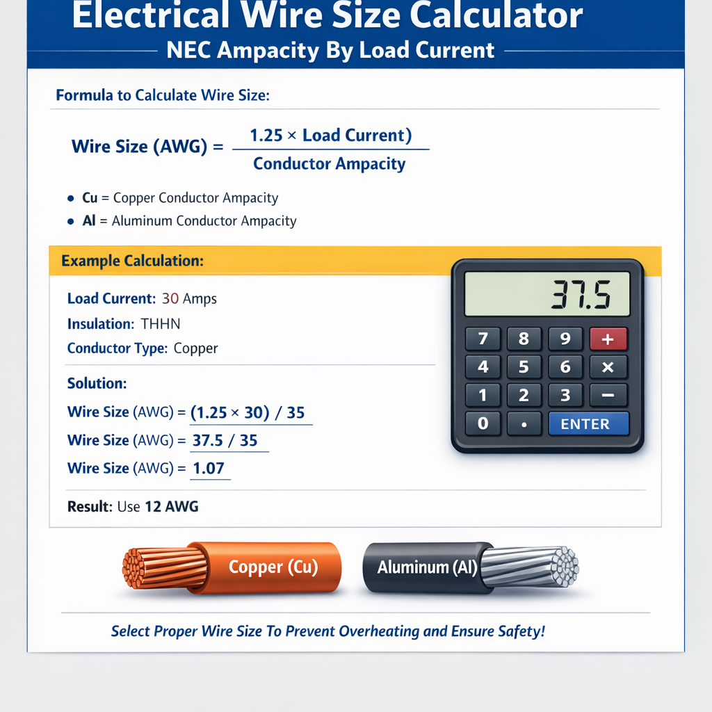
Electrical Wire Size Calculator (NEC Ampacity by Load Current, Insulation, Copper/Aluminum)
Scope, objectives and regulatory context
This article explains how to determine electrical wire size using NEC ampacity principles, insulation types, and load current. It targets designers, installers, and engineers working with copper (Cu) and aluminum (Al) conductors and covers ampacity selection, correction factors, voltage drop, and practical worked examples.
The methodology follows NFPA 70 (NEC) rules for ampacity, conductor temperature ratings, and derating while clarifying applicable calculations and normative references.
NEC ampacity fundamentals and decision flow
Wire sizing is a sequence: determine load current, classify load (continuous or non-continuous), apply correction factors, select conductor with adequate ampacity, and verify voltage drop.
Key NEC concepts to apply
- Load current (I_load): the actual continuous or non-continuous operating current of the circuit.
- Continuous load: NEC defines continuous as 3 hours or more; continuous loads require conductor ampacity ≥ 125% of continuous current.
- Ampacity: current-carrying capacity of a conductor at a specified temperature without exceeding insulation temperature limits (NEC Table 310.15(B)(16)).
- Temperature limitations: terminals and equipment may require using the 60°C, 75°C or 90°C column depending on terminal ratings. Always use the lowest applicable column.
- Adjustment and correction factors: for more than three current-carrying conductors, ambient temperature other than 30°C, or higher/lower ambient temperatures.
- Voltage drop: recommended maximum 3% for branch circuits and 5% total circuit (NEC does not mandate but industry practice recommends).
General sizing formula and factor approach
Wire selection is determined by required ampacity after derivation from actual load and the combination of derating factors. Use the following structural formula to determine the minimum required conductor ampacity:
Formula: Areq = Iload × Fcont / (Ct × Cg × Co)
Where:
- Areq = required conductor ampacity (A)
- Iload = calculated load current (A)
- Fcont = 1.25 if the load is continuous (NEC 210.20(A), 215.2(A)(1)), otherwise 1.0
- Ct = temperature correction factor for conductor insulation based on ambient temperature and insulation rating (from NEC 310.15(B)(2)(a))
- Cg = grouping/ampacity adjustment factor for multiple current-carrying conductors (NEC 310.15(B)(3)(a))
- Co = other correction factors (e.g., for specific installation conditions; often 1.0 if none apply)
Typical values:
- Fcont = 1.25 (continuous) or 1.0 (non-continuous)
- Ct examples: for 75°C insulation at 40°C ambient, Ct ≈ 0.91 (use NEC correction tables)
- Cg examples: for 4–6 current-carrying conductors in a raceway, Cg ≈ 0.8–0.7 (per NEC 310.15(B)(3)(a) table)
Voltage drop calculation and incorporation
Even after meeting ampacity, voltage drop must be verified. Designers typically restrict branch circuit voltage drop to ≤ 3% and feeder + branch ≤ 5%.
Single-phase voltage drop formula:
Vdrop = 2 × I × R × L
Three-phase voltage drop formula (line-to-line):
Vdrop = √3 × I × R × L
Where:
- Vdrop = voltage drop (V)
- I = circuit current (A)
- R = conductor resistance per unit length (Ω/ft or Ω/m) at operating temperature
- L = one-way length of conductor (ft or m)
- Note: if using impedance (Z) instead of R, include reactance: use Vdrop = √3 × I × Z × L for three-phase.
Typical resistance values (copper) per 1000 ft used for calculations:
| AWG | Resistance (Ω/1000 ft) @ 20°C (Cu) | Approx. R factor for temperature correction |
|---|---|---|
| 14 | 2.525 | increase with temp |
| 12 | 1.588 | increase with temp |
| 10 | 0.999 | increase with temp |
| 8 | 0.628 | increase with temp |
| 6 | 0.395 | increase with temp |
| 4 | 0.2485 | increase with temp |
| 2 | 0.1563 | increase with temp |
| 1 | 0.1239 | increase with temp |
| 1/0 | 0.0983 | increase with temp |
| 2/0 | 0.0779 | increase with temp |
| 3/0 | 0.0618 | increase with temp |
| 4/0 | 0.0490 | increase with temp |
Resistance values above are typical cold values; use temperature-corrected resistance for long runs or high ambient temperatures. Aluminum conductors have approximately 1.6 times the resistance of copper of equivalent cross-sectional area and require larger sizes to match ampacity and voltage drop.
NEC table excerpts and typical ampacity selections
NEC Table 310.15(B)(16) lists ampacities for common conductors in 60°C, 75°C and 90°C columns. Termination temperature ratings (equipment) control which column may be applied. The following tables provide common, widely-used practical ampacity figures for Cu and Al conductors for quick selection (informational). Verify against current NEC and manufacturer data for final design.
| Conductor | Typical Ampacity (Cu) — 75°C column (A) | Typical Ampacity (Al) — 75°C column (A) | Common Use |
|---|---|---|---|
| 14 AWG | 25 | N/A | Small branch circuits (NEC 240.4 limits to 15 A) |
| 12 AWG | 30 | 20 (Al eq. ≈ 12 AWG Al not typical) | Branch circuits (NEC 240.4 limits to 20 A) |
| 10 AWG | 35 | 30 | Small appliances, 30 A circuits |
| 8 AWG | 50 | 40 | Cooktops, small feeders |
| 6 AWG | 65 | 50 | Large branch circuits, small feeders |
| 4 AWG | 85 | 65 | Service feeders, larger loads |
| 2 AWG | 115 | 90 | Feeder circuits, small services |
| 1/0 AWG | 150 | 125 | Main feeders, branch to large loads |
| 4/0 AWG | 230 | 195 | Large service conductors |
Note: NEC small conductor rules (NEC 240.4(D)) may restrict allowable overcurrent protection on conductors sized by the table. Always check both ampacity tables and small conductor rules.
Temperature and grouping correction factors
NEC requires correction of ampacity for ambient temperature and for more than three current-carrying conductors in the same raceway or cable.
Ambient temperature correction
Use NEC correction factors found in 310.15(B)(2)(a) (typical example values):
- For 75°C rated insulation: 30°C ambient factor = 1.00 (base); at 40°C ambient factor ~0.91; at 50°C factor ~0.82. Always consult the NEC table for exact multipliers.
Grouping / number of conductors adjustment
The NEC 310.15(B)(3)(a) table provides multipliers depending on number of current-carrying conductors above 3. For example:
- 4–6 conductors: multiply ampacity by 80% (0.80) in many cases
- 7–9 conductors: multiply by 70% (0.70)
- Over 9 conductors: lower multipliers apply (e.g., 0.50–0.45 depending on count).
Always multiply the table ampacity by these factors and ensure resulting ampacity ≥ required Areq. If not, increase conductor size to the next allowed ampacity and re-evaluate.
Step-by-step sizing workflow
- Calculate connected load and determine maximum continuous and non-continuous currents (Iload).
- Apply continuous-load multiplication (×1.25 for continuous loads per NEC).
- Determine available terminal/equipment temperature rating and select appropriate NEC ampacity column (60°C, 75°C or 90°C).
- Apply ambient temperature correction factor Ct from NEC table.
- Apply grouping/number-of-conductors correction factor Cg from NEC table.
- Compute required ampacity Areq (Iload × Fcont / (Ct × Cg)).
- Select a conductor size whose tabulated ampacity (after factoring adjustments, or using unadjusted then adjusting selection) meets or exceeds Areq, considering terminal temperature rating limitations.
- Check voltage drop: compute Vdrop and ensure percent drop ≤ recommended limits (3% branch, 5% total). If not acceptable, increase conductor size and re-check ampacity and termination limits.
- Verify protection device coordination and NEC small conductor rules for maximum OCPD sizes.
Real-world example 1 — Single-phase branch circuit with voltage drop
Scenario: A 240 V electric water heater has a continuous load of 28 A. Run length is 75 ft one-way (150 ft round trip) using copper conductors in conduit, ambient temperature 30°C. Equipment terminations are rated 75°C. Limit voltage drop to ≤ 3%.
Step calculations
- Iload = 28 A (continuous). Apply continuous multiplier: Fcont = 1.25 → design current = 28 × 1.25 = 35 A.
- Ambient = 30°C, using 75°C column: Ct = 1.00 (base) because 30°C is base condition.
- Number of current-carrying conductors = 2 (hot and hot) in conduit — if neutral is not current carrying for multiwire, adjust accordingly; assume Cg = 1.00.
- Required ampacity Areq = 35 A / (1.00 × 1.00) = 35 A.
- From typical ampacity table (75°C column): 10 AWG Cu ≈ 35 A (typical table gives 35 A). However NEC 240.4(D) limits 10 AWG to 30 A? Actually NEC 240.4(D) permits 10 AWG to be protected up to 30 A for small conductor rules—this is critical: the installer must comply with NEC 240.4(D) small conductor ratings. Because this design requires 35 A, a larger conductor (8 AWG Cu) must be selected to allow a standard OCPD and ampacity.
- Select 8 AWG Cu: typical ampacity 50 A (75°C column), which exceeds 35 A. OCPD sized per circuit type (e.g., 40 A breaker could be used if allowed by appliance connection rules; verify appliance terminal ratings).
- Voltage drop check: use single-phase formula Vdrop = 2 × I × R × L (use R per ft). For 8 AWG Cu, R ≈ 0.000628 Ω/ft (0.628 Ω per 1000 ft). L (one-way) = 75 ft; round trip factor accounted by 2 in formula.
- Compute Vdrop: Vdrop = 2 × 28 A × 0.000628 Ω/ft × 75 ft = 2 × 28 × 0.000628 × 75 ≈ 2 × 28 × 0.0471 ≈ 2 × 1.319 ≈ 2.638 V.
- Percent voltage drop = (2.638 V / 240 V) × 100% ≈ 1.1% — within 3% target.
Result: 8 AWG Cu is the practical choice (meets ampacity after continuous requirement, meets voltage drop, and permits standard OCPD coordination). Verify appliance terminal ratings; if appliance listing allows smaller protection per appliance instruction, follow listed instructions per NEC 110.3(B).
Real-world example 2 — Three-phase feeder with derating and aluminum alternative
Scenario: Industrial three-phase 480 V feeder supplies a continuous load of 120 A, run length 200 ft one-way (400 ft round trip). Ambient temperature 40°C; conduit contains 6 current-carrying conductors (3 phase + 3 neutrals or other circuits) resulting in grouping derating. Termination equipment rating is 75°C. Consider both copper and aluminum options and keep voltage drop ≤ 3% (line-to-line).
Step calculations
- Iload = 120 A (continuous) → Fcont = 1.25 → design current = 150 A.
- Ambient 40°C, 75°C column: Ct ≈ 0.91 (typical NEC correction for 40°C with 75°C insulation — confirm with table).
- Number of current-carrying conductors = 6. NEC grouping factor for 4–6 conductors ≈ 0.8 (Cg = 0.80).
- Compute required ampacity: Areq = 150 A / (0.91 × 0.80) = 150 / 0.728 = ≈ 206.04 A.
- Select conductor ampacity ≥ 206 A using 75°C column.
- Check typical ampacity table: Cu 3/0 ≈ 200 A, Cu 4/0 ≈ 230 A. Therefore choose Cu 4/0 (230 A) to satisfy ampacity after derating.
- Now check voltage drop for 3-phase: Vdrop = √3 × I × R × L. Use R for 4/0 Cu ≈ 0.0490 Ω/1000 ft → R ≈ 0.0000490 Ω/ft. I = 120 A (the actual running current) or should we use design current? Voltage drop is based on operating current, not 125% factor (once conductor selected). Use I = 120 A.
- Compute Vdrop: Vdrop = 1.732 × 120 A × 0.0000490 Ω/ft × 200 ft ≈ 1.732 × 120 × 0.0098 ≈ 1.732 × 1.176 ≈ 2.036 V.
- Percent drop = (2.036 V / 480 V) × 100% ≈ 0.42% — well within 3%.
- Aluminum option: to achieve ≥ 206 A ampacity at 75°C, check typical Al sizes: 250 kcmil Al has typical ampacity ~255 A (75°C), 4/0 Al ~195 A — insufficient. Therefore choose 250 kcmil Al if wanting to use aluminum (size depends on catalog). Verify manufacturer chart: 250 kcmil Al (XHHW-2) often has ampacity ≈ 255 A at 75°C.
- Voltage drop with 250 kcmil Al: assume R ≈ 0.000078 Ω/ft (aluminum ~1.6× copper for same area). Vdrop = 1.732 × 120 × 0.000078 × 200 ≈ 1.732 × 120 × 0.0156 ≈ 1.732 × 1.872 ≈ 3.24 V → 0.675% drop ≈ acceptable.
Result: Copper 4/0 or Aluminum 250 kcmil are practical options. Copper 4/0 provides comfortable margin; aluminum requires larger cross-section but may be cost-effective for very large feeders. Always confirm ampacity with the actual product datasheet and current NEC edition.
Other practical constraints and coordination
- Terminal ratings: even if a conductor's insulation is rated 90°C, the equipment terminal may be rated 60°C or 75°C. Use the lowest applicable ampacity column for final selection (NEC 110.14(C)).
- Overcurrent protection coordination: conductor ampacity must be adequate for the selected OCPD, and small conductor rules may limit the maximum OCPD for certain AWG sizes (NEC 240.4).
- Torsional, mechanical and installation constraints: conduit fill, bending radius, and ampacity reduction due to thermal grouping in conduits can impact final selection.
- Harmonic currents and neutral sizing: for circuits with harmonics, neutral may be a current-carrying conductor and must be included in derating counts. Multipliers and neutral sizing rules (NEC 310.15(B)(5)) apply.
- Temperature-rise within bundling or enclosed spaces: cable tray and duct bank configurations can further reduce ampacity; consult manufacturer and NEC Annexes.
Practical tips for designers and installers
- Always refer to the current edition of NFPA 70 (NEC) and local amendments before final sizing.
- Use manufacturer ampacity tables for the exact cable/insulation type and consider long-run temperature-corrected resistances for precise voltage drop calculations.
- When using aluminum conductors, provide effective corrosion protection at terminations and ensure correct torque values and connectors.
- Document all assumptions: ambient temperature, conductor counts, length, load type (continuous or not), and equipment terminal ratings.
- Perform both ampacity check and voltage drop calculation; both conditions are required for reliable design.
Regulatory and standards references
- NFPA 70, National Electrical Code (NEC) — latest edition. See NEC Table 310.15(B)(16) for conductor ampacity tables: https://www.nfpa.org/
- NEC 110.14 — Electrical connections and use of terminal ratings (important for applying ampacity columns).
- NEC 240.4 — Protection of conductors; NEC 240.4(D) small conductor rules.
- NEC 310.15(B)(3)(a) — Adjustment factors for more than three current-carrying conductors.
- IEEE Std 141 (Red Book) and IEEE Std 142 (Green Book) — grounding and design guidance for power systems.
- IEC 60287 — Electrical cables — calculation of the continuous current rating of cables (useful for international practice): https://www.iec.ch/
- Manufacturer conductor and cable datasheets (e.g., Southwire, Prysmian, Nexans) for real ampacity and resistance: https://www.southwire.com/
Common FAQs and clarifications
Does ampacity equal breaker size?
Not directly. Ampacity is the conductor’s allowable current-carrying capacity. Overcurrent device selection must protect the conductor (NEC 240) and may be limited by small conductor rules; sometimes the breaker is sized per load and the conductor is upsized to suit the breaker while still meeting ampacity and voltage drop requirements.
When do I use 60°C vs 75°C vs 90°C tables?
Use the terminal/equipment rating (lowest rated connection) — for many devices the 75°C column is applicable for modern equipment, but older terminals may be rated 60°C. Always use the lowest applicable rating for final ampacity selection unless the equipment is listed for higher temperatures.
Can I rely on a single rule-of-thumb?
No. Wire sizing must account for actual load, continuous status, ambient temperature, conductor grouping, voltage drop, terminal ratings, and local code amendments. Use documented calculations for compliance.
Summary of procedures (concise checklist)
- Calculate actual load; identify continuous components.
- Apply continuous multiplier (×1.25) where required.
- Determine ambient temperature and conductor grouping factors.
- Select ampacity column based on terminal ratings.
- Calculate Areq and select conductor with tabulated ampacity ≥ Areq.
- Perform voltage drop calculations; if > limit, increase conductor size.
- Verify OCPD selection against conductor protection rules and terminal listings.
- Document references, manufacturer data, and assumptions for inspection and commissioning.
Further reading and authoritative links
- NFPA—National Fire Protection Association, NFPA 70 (NEC): https://www.nfpa.org/
- IEC standards on cable current rating (IEC 60287): https://www.iec.ch/
- IEEE resources for grounding, power distribution, and cable design: https://standards.ieee.org/
- Manufacturer ampacity and resistance tables (examples): Southwire — Technical Resources: https://www.southwire.com/
- OSHA electrical safety resources and general guidance: https://www.osha.gov/
Designers must always cross-check these methods with the current NEC edition, relevant local codes, and manufacturer data. When in doubt, engage a licensed electrical engineer for final designs and sign-off.