This calculator expedites fixed-appliance load estimation for engineering, compliance and design decision workflows efficiently worldwide.
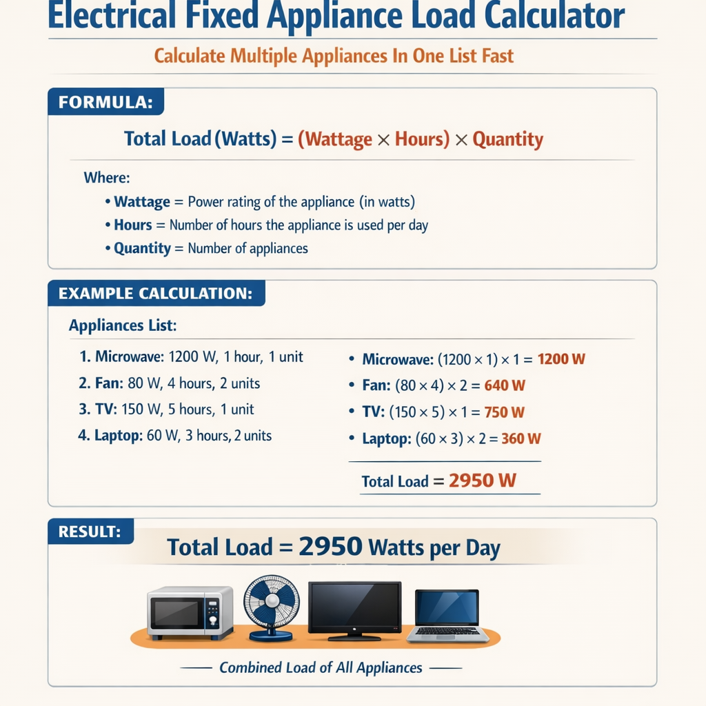
Engineers can calculate multiple appliances in one list rapidly with accurate diversification and demand factors.
Fixed Electrical Appliance Load Calculator (Total Demand Load and Estimated Current)
Purpose and scope of a fixed-appliance load calculator
A fixed-appliance load calculator converts lists of permanent electrical appliances into a consolidated electrical load schedule suitable for circuit, distribution, and protection design. It standardizes input data, applies normative demand and diversity rules, performs power factor and harmonic adjustments, and outputs conductor, protective device, and voltage-drop results for design verification.
Key technical concepts
1. Appliance classification
- Fixed appliances: equipment permanently installed (e.g., HVAC, ovens, water heaters, motors).
- Plug-in or portable loads are normally excluded from fixed-appliance lists unless specifically hardwired.
- Continuous loads: equipment operating for three hours or more, affecting breaker sizing and demand factors.
2. Electrical quantities and relationships
Fundamental formulae used in the calculator are expressed in simple HTML notation. Each formula is followed by explanation and typical values.
- P = Real power (W or kW).
- V = Line voltage (V). Typical values: 120 V, 230 V, 400 V, 480 V.
- I = Current (A).
- PF = Power factor (unitless, typical 0.8–1.0 for resistive loads; motors 0.7–0.95).
- Use this to derive current from known power and voltage using typical PF values.
- S = Apparent power (VA or kVA). For three-phase calculations: S = √3 × V_L × I_L.
- Typical three-phase line-to-line voltages: 400 V (EU), 480 V (US industrial), 415 V.
- V_LL = Line-to-line voltage (V).
- I_line = Line current (A).
- Used for transformer sizing.
- Typical PF: 0.8–0.95 depending on load composition.
- VD% = percentage voltage drop (approximate single-phase loop method).
- L = one-way conductor length in meters.
- I = current in amperes.
- R = conductor resistance per km (Ω/km) or per meter converted appropriately.
- Typical acceptable VD%: 3–5% for final circuits, 1–3% for sensitive equipment.
Algorithmic flow of the calculator
- Accept a list of appliances with attributes: name, rated power (W or kW), voltage, phase, duty cycle, continuous flag, power factor, quantity, and location.
- Normalize units (convert W ↔ kW, V phases, quantity multiplication).
- Apply individual appliance correction factors (temperature derating, altitude, harmonic currents if specified).
- Apply relevant normative demand factors or diversity factors based on jurisdiction rules or engineered diversity tables.
- Aggregate to circuit and sub-distribution levels; compute currents, apparent power, and reactive requirements.
- Size conductors and protective devices per selected standard rules (e.g., NEC, IEC) and evaluate voltage drop.
- Provide detailed output: tabulated per-appliance contributions, grouped sums, and equipment sizing recommendations.
Normative demand and diversity methods
Different standards use distinct diversity/demand methodologies. The calculator supports selectable normative profiles to accommodate project requirements.
- NEC (NFPA 70) method: applies continuous load multipliers, sizing rules for kitchens and ranges, and specific motor rules.
- IEC 60364 / EN 60898: uses diversity tables and engineering judgement for residential/commercial appliances.
- Local standards (e.g., BS 7671, AS/NZS 3000) specify demand factors for groups of circuits and particular fixed appliances.
Input data best practices
- Specify rated power (nameplate) and not estimated values where possible.
- Include duty cycle or diversity percentages for loads that do not run continuously.
- Provide measured or manufacturer-provided power factor when available.
- Flag continuous loads explicitly for automatic continuous-load multipliers (e.g., 125% sizing where required).
- Include quantity and grouping to allow diversity calculations (e.g., ten identical ovens in a kitchen zone).
Tables of common fixed appliance loads
| Appliance | Typical Rating (W) | Voltage | Power Factor (typ) | Continuous? |
|---|---|---|---|---|
| Domestic electric oven (single) | 3000–5000 | 230 V | 0.95 | No |
| Commercial convection oven | 8,000–20,000 | 400 V / 3φ | 0.95 | No |
| Electric water heater (residential) | 2000–4500 | 230 V | 1.0 | Yes |
| Air handling unit (AHU) fan motor | 1,000–25,000 | 400 V / 3φ | 0.85–0.95 | Often |
| Chiller compressor (per ton) | 3,200–5,000 per ton | 400 V / 3φ | 0.75–0.9 | Often |
| Electric vehicle charger (Level 2) | 3,300–7,200 | 230 V / 1φ | 0.98 | No |
| Commercial dishwasher | 3,000–12,000 | 230 V/400 V | 0.95 | No |
| Appliance Group | Quantity | Connected Load (kW) | Demand Factor (example) | Design Load (kW) |
|---|---|---|---|---|
| Residential cooking appliances | 10 | 5 × 10 = 50 | 0.30 (per typical demand table) | 15.0 |
| Water heaters | 8 | 3 × 8 = 24 | 1.00 (continuous) | 24.0 |
| AHU motors | 6 | 4 × 6 = 24 | 0.60 (diversity) | 14.4 |
Applying diversity and demand factors — worked methodology
When multiple appliances are listed together, the calculator can apply either fixed normative demand factors (tabular) or engineered diversity. The difference is:
- Tabular demand factors reduce aggregate connected load by a prescribed percentage depending on quantity and type.
- Engineered diversity uses measured or probabilistic models to estimate coincident usage and may be optimized for energy efficiency.
Real-world example 1: Small commercial kitchen bank (detailed)
Scenario: Commercial kitchen with multiple ovens, dryers, dishwashers, and service water heaters. Objective: compute main distribution current and select transformer rating and main protective device.
Input list (sample):
- 3 × Commercial convection ovens: each 12 kW, 400 V, 3φ, PF 0.95, intermittent.
- 2 × Dishwashers: each 6 kW, 230 V, single-phase, PF 0.95, intermittent.
- 2 × Electric water heaters: each 9 kW, 230 V, continuous-ish, PF 1.0.
- 1 × AHU fan: 5 kW, 400 V, 3φ, PF 0.9, continuous during service hours.
- Ovens: 3 × 12 kW = 36 kW.
- Dishwashers: 2 × 6 kW = 12 kW.
- Water heaters: 2 × 9 kW = 18 kW.
- AHU: 5 kW.
- Total connected = 36 + 12 + 18 + 5 = 71 kW.
- Use a kitchen demand table: assume 36 kW ovens group has demand factor 0.65 for multiple ovens (this is illustrative; verify with local code).
- Dishwashers diversity 0.5 due to staggered duty.
- Water heaters continuous — demand 1.0.
- AHU no diversity applied for essential ventilation during hours — 1.0.
- Ovens design load = 36 × 0.65 = 23.4 kW.
- Dishwashers design load = 12 × 0.5 = 6.0 kW.
- Water heaters design load = 18 × 1.0 = 18.0 kW.
- AHU design load = 5 × 1.0 = 5.0 kW.
- Subtotal design load = 23.4 + 6.0 + 18.0 + 5.0 = 52.4 kW.
- Assume supply voltage = 400 V line-to-line, and balanced distribution.
- Estimate combined power factor PF_combined = 0.92 (weighted average based on load composition).
- kVA = kW / PF = 52.4 / 0.92 = 56.96 kVA.
- Line current I_line = (kVA × 1000) / (√3 × V_LL) = (56.96 × 1000) / (1.732 × 400) ≈ 82.3 A.
- Transformer nominal kVA: select next standard size, e.g., 75 kVA to allow capacity and future growth.
- Main protective device: apply continuous load correction if any continuous portion exists. If water heaters and AHU are considered continuous (more than 3 hours), continuous portion = 18 + 5 = 23 kW.
- NEC-style continuous adjustment: design current = calculated current × 125% for continuous portion embedded in load; however, if the continuous portion is part of total, ensure conductor and protective device accommodate combined adjusted current. For conservative sizing, increase I_line by factor (1.25 × continuous_fraction + noncontinuous_fraction). For brevity, choose protective device rated 125 A to cover starting currents and selectivity.
- Assume feeder length L = 35 m, conductor copper 4-core 35 mm2 with R ≈ 0.524 Ω/km = 0.000524 Ω/m (example resistance depends on standard tables).
- Compute approximate VD% using three-phase formula approximate: VD% ≈ (√3 × I_line × (R_cond_per_m) × L) / V_LL × 100.
- Plug values: numerator = 1.732 × 82.3 × 0.000524 × 35 ≈ 2.62; VD% ≈ (2.62 / 400) × 100 ≈ 0.655%.
- Voltage drop is acceptable (below 3%).
Real-world example 2: Multi-residential distribution panel (detailed)
Scenario: A residential building with 12 apartments, communal water heater, and building services. Objective: determine main incoming cable rating and apply residential demand rules.
Input list:- 12 × apartments: each connected load for fixed appliances and lighting combined assumed 5.5 kW per apartment (connected).
- Communal water heater: 9 kW continuous.
- Lobby AHU and pumps: combined 6 kW.
- Electric vehicle charging: 4 × Level 2 chargers at 7.2 kW but expected diversity 0.4 due to usage patterns.
- Apartments total connected = 12 × 5.5 = 66.0 kW.
- Water heater = 9.0 kW.
- Services = 6.0 kW.
- EV chargers connected = 4 × 7.2 = 28.8 kW.
- Total connected = 66 + 9 + 6 + 28.8 = 109.8 kW.
- Use a residential diversity table: first apartment at 100% and incremental reduction after, or use aggregated table directly. For simplicity apply a building-level demand factor of 0.55 for the 12 apartments (illustrative).
- EV chargers demand factor 0.4 (specified).
- Water heater continuous 1.0.
- Services 1.0.
- Apartments design = 66 × 0.55 = 36.3 kW.
- EV chargers design = 28.8 × 0.4 = 11.52 kW.
- Subtotal design = 36.3 + 11.52 + 9 + 6 = 62.82 kW.
- kVA = 62.82 / 0.95 = 66.13 kVA.
- I_line = (66.13 × 1000) / (1.732 × 400) ≈ 95.6 A.
- Main incoming cable: select 95 mm2 copper or appropriate aluminium equivalent depending on installation method and derating; check thermal correction factors, grouping, and installation temperature.
- Main protective device: choose 125 A or 160 A depending on coordination and selectivity policy; allow for future load growth.
- Assume feeder length 50 m, typical cable R = 0.2 Ω/km (varies by conductor size). Compute VD using three-phase formula and ensure below 3%.
- Apply rounding to next standard sizes and check manufacturer tables for cable ampacity with correction factors.
Advanced considerations
Power factor correction and reactive power
When loads contain inductive components (motors, ballasts), compute reactive power Q and resultant kVA for transformer sizing.
- P = real power (kW).
- PF = power factor (unitless).
- kVA = √(P^2 + Q^2).
Harmonics and non-linear loads
- Non-linear loads (VFDs, electronic ballasts, large UPS) generate harmonic distortion that increases conductor heating and neutral currents. Calculate harmonic currents using manufacturer THDi data and apply derating factors.
- Neutral sizing: for significant triplen harmonics in three-phase three-wire systems, neutral can carry high currents—size neutrals per standard guidance when harmonic content is expected.
Start-up currents and motor starting
- Large motors can draw several times locked-rotor current; the calculator should flag starting current and advise on inrush mitigation (soft starters, VFDs, diversity assumptions for simultaneous starting).
Temperature, altitude and derating
- Adjust conductor ampacity for ambient temperature, grouping, and altitude per relevant standard tables.
Implementation details for a fast multi-appliance list calculator
- Use a normalized internal unit system (kW, V, A, PF) for speed.
- Pre-populate appliance library with typical ratings and allow quick override.
- Enable batch entry via spreadsheet import (CSV) with column mapping to reduce manual input time.
- Support selectable normative profiles (NEC, IEC, BS, AS/NZS) and custom user-defined demand tables.
- Provide immediate feedback on critical constraints: continuous load exceedance, voltage drop warnings, harmonic flags, and protective device conflicts.
- Cache intermediate calculations to allow live recalculations when a single item is edited.
Reporting outputs and verification
- Generate per-appliance contribution table and a grouped summary table with connected, design, and demand values.
- Provide conductor sizing suggestions with installation method notes and required correction factors.
- Produce breaker and transformer sizing recommendations including kVA, inrush allowance, and PF correction suggestions.
- Include a traceable calculation log for compliance and peer-review.
Typical error sources and mitigation
- Incorrect appliance ratings: always use nameplate or manufacturer data; flag estimates.
- Misapplied diversity: choose correct normative table and document justification for engineering variances.
- Neglecting harmonics: ask for THDi from vendors when loads have electronics or VFDs.
- Forgetting continuous load rules: automatically detect and apply continuous multipliers when run-time >= 3 hours.
Regulatory references and authoritative sources
Design and calculation must reference the appropriate jurisdictional standards. Relevant authorities include:
- NFPA 70: National Electrical Code (NEC) — https://www.nfpa.org/NEC
- IEC 60364: Low-voltage electrical installations — https://www.iec.ch
- BS 7671: Requirements for Electrical Installations (IET Wiring Regulations) — https://electrical.theiet.org/
- IEEE standards for power quality and harmonics (IEEE 519) — https://standards.ieee.org/standard/519-2014.html
- Local utility connection rules and transformer selection guidelines (consult local DNO/utility).
Data export, audit trail, and interoperability
- Export formats: CSV for spreadsheets, PDF for reports, and XML/JSON for BIM and electrical design software integration.
- Maintain an audit trail with timestamped changes, user IDs, and versioning for design reviews and approvals.
- Integrate with single-line diagram tools to auto-annotate feeders and protective devices based on calculator outputs.
User interface and UX recommendations for rapid multi-appliance entry
- Allow templates: kitchen bank, residential block, hotel rooms, mechanical plantrooms.
- Inline validation: flag missing PF, voltage, or quantity with tooltips suggesting typical values.
- Bulk actions: apply diversity rules to selected groups, replicate appliance entries with offsets.
- Provide an appliance library searchable by keyword and filtered by category, manufacturer, or normative class.
Best-practice checklist before finalizing design
- Confirm nameplate values and PF with manufacturers.
- Verify load duty cycles and continuous operation flags.
- Check harmonic content and neutral loading for non-linear loads.
- Apply appropriate temperature and grouping derating factors to conductor ampacity.
- Assess coordination and selectivity of protective devices at upstream and downstream levels.
- Validate voltage drop for each final circuit and main feeder against acceptable limits.
- Document all normative references and any engineering deviations.
Summary of deliverables from the calculator
- Per-appliance summary with connected and design (after demand) loads.
- Aggregated kW, kVA, and line currents per distribution level.
- Recommended transformer kVA and nominal tap selection.
- Suggested conductor sizes with detailed voltage drop calculations.
- Recommended protective device sizes and notes on continuous load requirements.
- Harmonic advisory if THDi thresholds exceeded and neutral derating suggestions.
Further reading and standards links
- NFPA 70 (NEC): https://www.nfpa.org/NEC — essential for U.S. installations and breaker sizing.
- IEC 60364 series: https://www.iec.ch — international guidance on low-voltage installation design.
- IEEE 519: https://standards.ieee.org/standard/519-2014.html — guidelines on harmonic control in electrical power systems.
- British Standards Institution (BS 7671): https://electrical.theiet.org/ — UK wiring regulations and diversity guidance.
- Local utility and distribution network operator (DNO) documentation — consult for connection agreements and transformer selection.
Using a structured, rule-based fixed-appliance load calculator reduces design errors, accelerates approvals, and provides auditable calculations for electrical projects across building types and jurisdictions.