Accurate fuse sizing protects circuits, prevents nuisance trips, and ensures equipment thermal stability and reliability.
This guide explains rules of thumb, standard sizes, calculations, and examples for practical fuse selection.
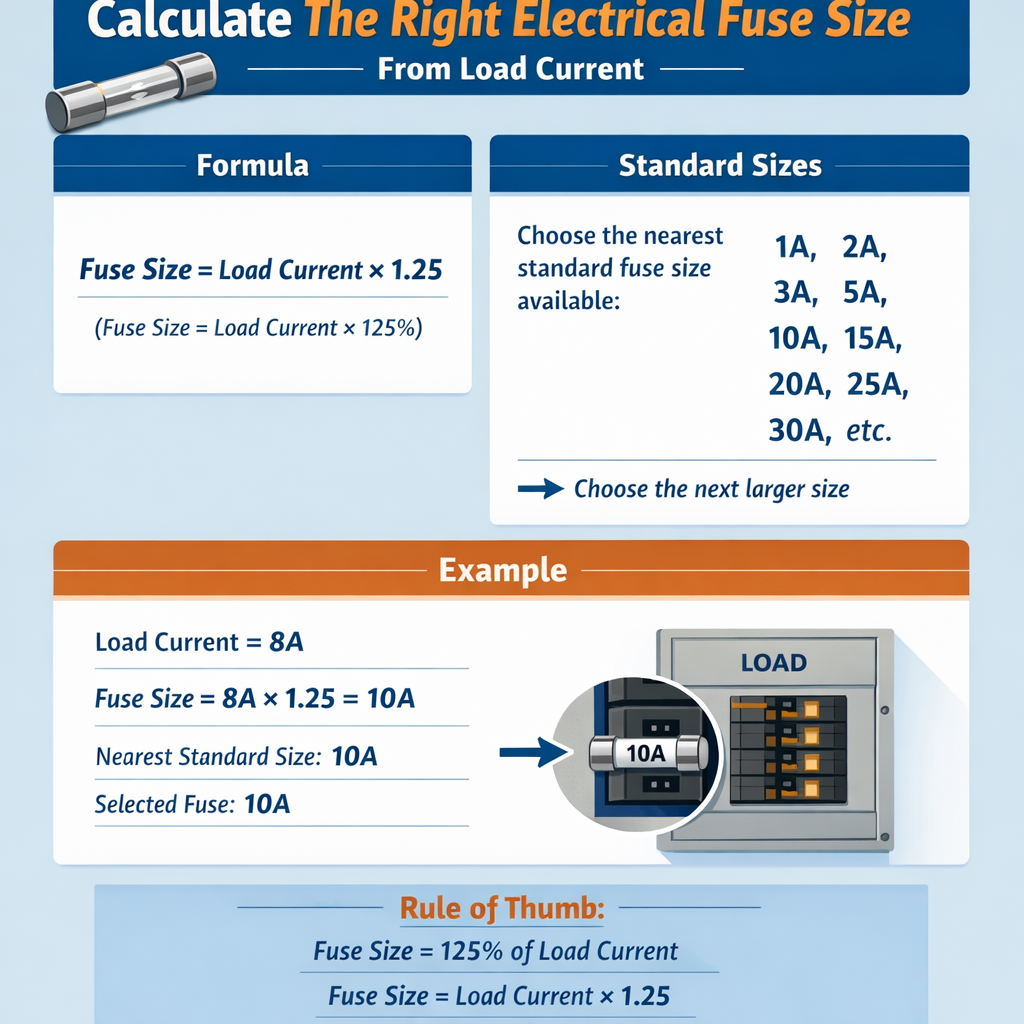
Fuse Size Calculator from Load Current and Standard Fuse Ratings (Rule-of-Thumb Method)
Fundamentals of determining fuse size from load current
A fuse is an overcurrent protective device that operates by melting a fusible element when current exceeds a thermal/time threshold. Proper sizing balances two objectives: ensure continuous and transient currents flow uninterrupted, and reliably interrupt short-circuit or sustained overload currents without damaging conductors or equipment. Fuse selection requires electrical calculations and application-specific considerations: continuous load percentage, inrush or start-up currents, ambient temperature, conductor ampacity, coordination with upstream devices, and relevant standards (NEC/NFPA 70, IEC 60269, UL 248). Key parameters to gather before any calculation:- Steady-state load current (I_load) — measured or computed from power and voltage.
- Load type — resistive, inductive (motors, transformers), electronic supplies (inrush-limited).
- Duty cycle — continuous (≥3 hours) or non-continuous.
- Inrush/starting multiple and duration — locked-rotor or magnetizing current multipliers.
- System voltage and phase (single-phase or three-phase).
- Ambient temperature and enclosure derating requirements.
- Conductor size and ampacity; equipment and branch-circuit protection rules.
Basic electrical formulas for load current
If you know real power (P) and supply parameters, calculate steady current using:
Single-phase: I_load = P / (V × PF)
Three-phase (balanced): I_load = P / (sqrt(3) × V × PF)
Where variables are:
- P = real power in watts (W) or kilowatts (kW) — if using kW, convert to W by multiplying by 1000.
- V = line-to-line voltage in volts (V) for three-phase, line voltage for single-phase.
- PF = power factor (unitless, typically 0.8–1.0; PF = 1 for purely resistive).
- sqrt(3) = 1.7320508 (approx.), used for three-phase power conversion.
- Small motor PF ~ 0.8–0.9, efficiency ~ 0.85–0.95 (if converting mechanical output to electrical input).
- Resistive heater PF = 1.0.
- Electronics with switching supplies PF variable; use nameplate input or measured current.
Standards, normative constraints and regulatory rules of thumb
Fuse selection must comply with national and international standards and electrical codes. Primary references include:- NFPA 70 (NEC) — Articles 240 (Overcurrent Protection), 430 (Motors) and related tables. See https://www.nfpa.org/ (NFPA subscription may be required for full text).
- IEC 60269 series — Low-voltage fuses for industrial applications: classification, rated currents, clearance, and time-current testing. See https://www.iec.ch/.
- UL 248 series — Standard for fuses used in North America (fuse-links and fuseholders). See https://standardscatalog.ul.com/.
- IEEE standards and manufacturer time-current characteristic (TCC) curves for coordination guidance.
- Continuous loads: size overcurrent protective device at 125% of continuous load current (NEC general rule for branch-circuit conductors and OCPD sizing).
- Non-continuous resistive loads: choose the next higher standard fuse rating at or slightly above calculated load current.
- Inductive/equipment with inrush: use time-delay (slow-blow) fuses; allowable sizing often ranges 125%–135% or higher depending on inrush magnitude and duration — validate with TCC curves.
- Motor starting: follow NEC Article 430 and motor manufacturer nameplate; motor branch-circuit short-circuit and ground-fault protection and overload protection rules differ — consult tables and manufacturer data.
Standard fuse sizes — extensive reference tables
| Common standard fuse ampere ratings (North America & IEC overlap) |
|---|
| 0.1 A, 0.15 A, 0.2 A, 0.25 A, 0.3 A, 0.5 A, 0.75 A |
| 1 A, 1.25 A, 1.6 A, 2 A, 2.5 A, 3 A, 3.15 A |
| 4 A, 5 A, 6 A, 7 A, 8 A, 10 A, 12 A |
| 15 A, 16 A, 20 A, 25 A, 30 A, 32 A, 35 A |
| 40 A, 45 A, 50 A, 63 A, 70 A, 80 A, 90 A |
| 100 A, 110 A, 125 A, 140 A, 150 A, 175 A, 200 A |
| 225 A, 250 A, 300 A, 350 A, 400 A, 450 A, 500 A |
| 600 A, 700 A, 800 A, 1000 A (and larger custom values) |
| Typical fuse application & selection guide | Recommended selection rule (rule-of-thumb) |
|---|---|
| Resistive continuous loads (electric heaters, ovens) | Fuse rating = 125% × I_load; select next standard size. Verify conductor ampacity. |
| Electronic equipment with moderate inrush (SMPS) | Time-delay fuse; fuse rating ≈ 125%–150% × steady I_load; check TCC and inrush duration. |
| Motors (induction, compressor start) | Follow NEC Article 430 and motor nameplate; use time-delay fuses and TCC; expected fuse rating often between 135% and 300% of FLC depending on service and protection type. Verify with tables. |
| Transformers (inrush magnetizing current) | Time-delay fuses; fuse rating often 125%–200% of transformer rated current; confirm with manufacturer curves. |
| Short-term start/peak currents (e.g., capacitive banks) | Choose a fuse with sufficient I2t capacity or time-delay characteristics; consult manufacturer TCC. |
Derating considerations and ambient temperature
Fuse performance is affected by ambient temperature and enclosure conditions. Many fuse manufacturers publish ambient correction factors. Typical practice:- Ambient above 25 °C often requires derating — e.g., reduce continuous current rating by a temperature correction factor (manufacturer-specific).
- Bundled or enclosed conductors may require conductor ampacity derating, which constrains the maximum allowable fuse rating; fuse rating must not exceed conductor maximum allowed overcurrent protection.
- Altitude and ventilation may also affect derating for some devices.
Time-current characteristic (TCC) and coordination
Fuse selection is not only about steady-state current. The TCC curve defines how long a fuse will endure overload currents before opening. Important concepts:- Melting curve: time vs current where the fusible element melts.
- Interrupting rating (I.R.): maximum current the fuse can safely interrupt without damage.
- I2t rating: energy let-through, used to evaluate whether downstream components (like semiconductor devices) will be damaged during a fault event.
- Coordination: arranging upstream and downstream protection so one clears fault without unnecessary upstream device operation.
Step-by-step method to calculate a fuse size from load current
Follow a systematic approach:- Calculate steady-state load current using the formulas above.
- Determine whether the load is continuous. If continuous, apply 125% multiplier (NEC) as a baseline.
- Estimate inrush/starting current magnitude and duration from manufacturer data or measurement.
- Select fuse type: fast-acting (for low inrush) or time-delay/slow-blow (for significant inrush). Use time-delay for motors, transformers, and SMPS with high startup currents.
- Apply ambient and installation derating factors (conductor and fuse manufacturer recommendations).
- Compute candidate fuse rating: I_candidate = I_load × K_total (K_total accounts for 125% continuous plus additional margin for inrush as needed).
- Choose the next higher standard fuse rating from the standard sizes table that meets the candidate rating and does not violate conductor ampacity or manufacturer constraints.
- Verify using TCC: ensure the fuse will not blow under expected inrush and will clear short-circuits within acceptable times, and verify coordination and interrupting rating.
Formula summary (HTML-only)
I_load (single-phase) = P / (V × PF)
I_load (three-phase) = P / (sqrt(3) × V × PF)
For continuous loads: I_fuse_nominal ≈ 1.25 × I_load
General candidate selection: I_fuse_candidate = I_load × K_continuous × K_inrush × K_temp
- K_continuous = 1.25 if the load is continuous (typical NEC-based rule).
- K_inrush = multiplier to allow for inrush without nuisance blowing (depends on fuse type and inrush magnitude; typical rule-of-thumb 1.0–3.0; use manufacturer TCC).
- K_temp = ambient correction factor (manufacturer datasheet value <=1.0 for hotter enclosures).
Real-case Example 1 — Single-phase resistive heater (detailed)
Scenario: Industrial oven element rated 3.0 kW continuous at 240 V single-phase in an ambient-controlled cabinet (ambient ≤ 30 °C). No significant inrush (resistive). Conductor: copper, destination branch-circuit 60 °C rated terminals. Step 1 — Calculate steady-state current:I_load = P / (V × PF) = 3000 W / (240 V × 1.0) = 12.5 A
I_fuse_base = 1.25 × I_load = 1.25 × 12.5 A = 15.625 A
I_fuse_candidate = 15.625 A
- If using 16 A fuse: conductor must support 16 A continuous safely — e.g., 1.5 mm² copper typical ampacity (depending on insulation and temperature) maybe 15–18 A — check local code; 2.5 mm² copper typically rated 20–25 A and is safer.
- If using 20 A fuse: choose 12 AWG copper (20 A rating in US) or 2.5 mm² copper as conductor; ensures conductor ampacity is ≥ fuse rating.
- Recommended: 20 A time-delay or fast-acting fuse depending on element thermal behavior; in most installations a fast-acting 20 A fuse is acceptable because inrush is negligible.
- Document: I_load 12.5 A, selected fuse 20 A, conductor 2.5 mm² (or 12 AWG), verify upstream coordination and interrupting rating.
Real-case Example 2 — Three-phase induction motor with starting inrush
Scenario: 5.5 kW (7.5 HP) three-phase induction motor, supply 400 V line-to-line, nameplate power factor 0.85 and efficiency 0.90. Motor is used in a production line with frequent start/stop cycles. Locked-rotor current (LRC) from manufacturer = 6 × FLC (typical). The application requires branch-circuit short-circuit and ground-fault protection via fuses. Determine an appropriate fuse. Step 1 — Compute full-load current (FLC) electrical input:I_load = P_out / (sqrt(3) × V × PF × efficiency)
I_load = 5500 W / (1.732 × 400 V × 0.85 × 0.90)
I_load ≈ 5500 / 530.892 ≈ 10.36 A
Step 2 — Continuous vs non-continuous:- Motor duty: cyclic with frequent starts; motor is not necessarily continuous, but thermal effect of starting loads requires allowance.
I_fuse_base = 1.25 × I_load = 1.25 × 10.36 A = 12.95 A
- LRC = 6 × FLC = 6 × 10.36 A ≈ 62.16 A
- Duration: LRC persists for fractions of a second to a few seconds depending on starting method.
- Time-delay (gG / type) fuses for motors typically tolerate short surges. Manufacturer TCC needed. Rule-of-thumb: a time-delay fuse rated at 125%–200% of FLC may survive LRC for short time depending on fuse characteristics.
- It must not melt for the inrush current (≈62 A) with a given duration (for example, 0.5–2 seconds), and
- It must clear sustained overloads or faults sufficiently fast to protect conductors.
- Ensure conductor ampacity ≥ 15 A for continuous duty; if repetitive starts induce thermal stress, use larger conductor per NEC 430 and conductor derating rules.
- Confirm selected fuse complies with NEC maximum protective device allowances for motor branch-circuits (see NEC 430.52 and related tables for maximum permitted OCPD relative to motor FLC; professional judgment required).
Practical considerations, checklist and maintenance
When finalizing fuse selection, evaluate:- Interrupting rating (I.R.) — must equal or exceed available fault current at installation point.
- Coordination with upstream devices — verify selective coordination if required using TCC overlays.
- Physical form factor — cartridge, blade, miniature, high rupture capacity (HRC), etc., and compatibility with fuse holders.
- Fuse breaking capacity and network prospective fault current — oversized fuses with insufficient I.R. are unsafe.
- Environmental factors — humidity, corrosive atmospheres, vibration, and mechanical shock.
- Labeling and documentation — record the calculated load current, chosen fuse rating, TCC references, and compliance notes.
- Maintain spare fuses of correct type and rating on site. Do not substitute different class or lower interrupt rating fuses.
- Periodically inspect fuse holders and contacts for heating, oxidation, or mechanical looseness.
- When troubleshooting nuisance blows, measure steady-state and inrush currents, consult TCC, and consider whether thermal, mechanical, or electrical faults exist.
Common pitfalls and how to avoid them
- Using only steady-state current without examining inrush: verify with measurements or manufacturer data to prevent nuisance trips.
- Ignoring conductor ampacity limits: fuse rating must be coordinated with conductor sizing and insulation limits.
- Choosing a fuse with insufficient interrupting rating: always verify available short-circuit current and fuse I.R.
- Not checking time-current curves: fuses of the same ampere rating but different class or manufacturer behave differently.
- Mixing metric and North American standards carelessly: standard ratings differ; select according to locale and equipment compatibility.
Reference normative documents and authoritative links
- NFPA 70: National Electrical Code — Overcurrent Protection and Motor Sections (subscribe or consult the current edition): https://www.nfpa.org/
- IEC 60269 series — Low-voltage fuses: https://www.iec.ch/
- Underwriters Laboratories (UL) Standards for fuses (UL 248 series): https://standardscatalog.ul.com/
- IEEE PES and technical papers on coordination and TCC: https://ieeexplore.ieee.org/
- Manufacturer fuse technical guides (examples): Littelfuse product technical center — https://www.littelfuse.com/; Eaton Bussmann — https://www.eaton.com/us/en-us.html. (Use manufacturer TCCs for final verification.)
Further reading and practical tools
- Manufacturer time-current curve (TCC) catalogs and online selection tools — essential for precise selection and coordination.
- NEC handbooks and commentary — provide interpretation and worked examples for motor and branch-circuit protection.
- Software and coordination calculators — useful for overlaying TCCs and performing selectivity studies in complex power systems.
Key takeaways and engineering best practices
- Start with an accurate calculation of steady-state load current using P, V, and PF. Use the three-phase formula when appropriate.
- Apply the 125% rule-of-thumb for continuous loads as an initial baseline, but adjust for inrush and ambient conditions.
- Select fuse type (fast-acting vs time-delay) to match the nature of the load; always validate with manufacturer TCC curves.
- Ensure conductor ampacity and fuse interrupting ratings are compliant with code and safety margins.
- Document the calculation, selection rationale, and references to standards and manufacturer data for inspection and future maintenance.
- Run custom calculations for your specific load (provide P, V, PF, duty cycle, inrush).
- Overlay manufacturer TCCs for candidate fuse ratings and show coordination diagrams.
- Generate a printable selection worksheet tailored to IEC or NEC requirements.