This article explains ATS continuous rating calculation and transfer switch sizing for load current applications.
It covers optional generator check functions and transfer timing for reliable automatic changeover maintenance planning.
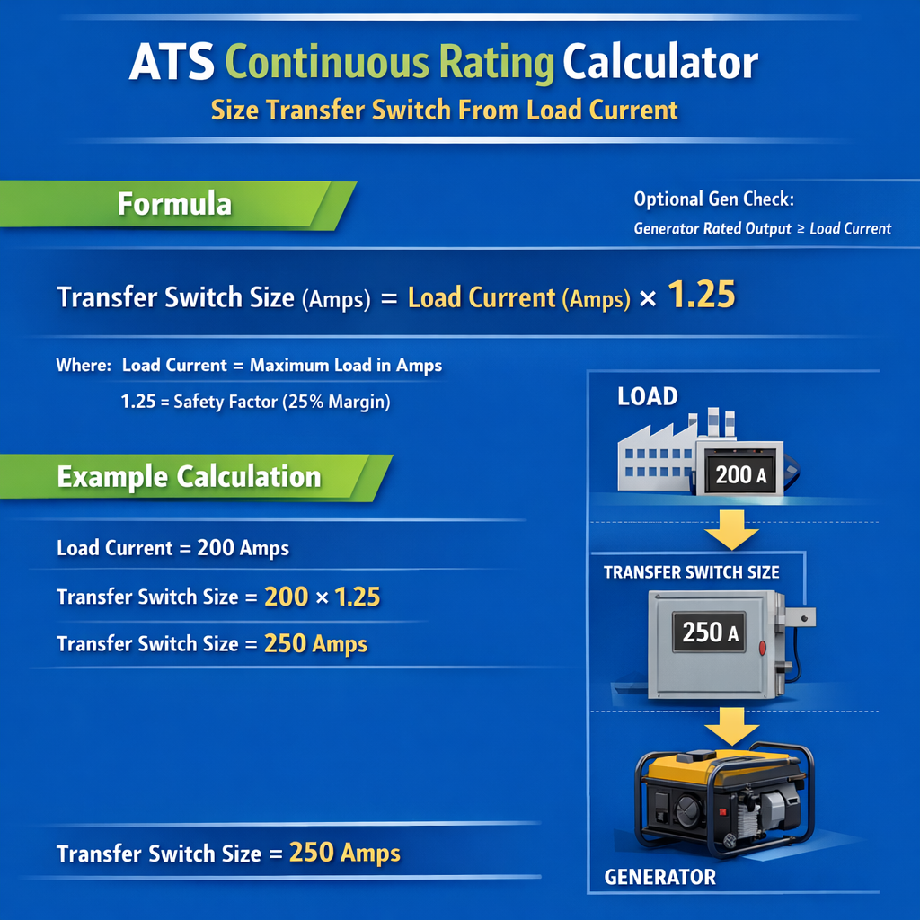
ATS Continuous Current Rating Calculator from Load Current with Optional Generator Check
Scope and applicability
This technical article targets engineers, specifiers, and installation personnel involved in automatic transfer switch (ATS) selection and sizing. It focuses on continuous rating determination and the optional generator check (gen‑check) function used to verify generator condition before transfer. Examples use international system units with common North American and IEC references.
Key definitions and operational concepts
Automatic Transfer Switch (ATS)
- Device that automatically transfers load between two power sources (normal and emergency/alternate).
- Continuous rating — the maximum current the ATS can carry continuously without thermal or mechanical degradation.
Continuous rating vs. short-time/standby rating
- Continuous rating: rating for sustained current (hours) with appropriate thermal management.
- Short-time or closing duty: ability to make/break fault currents and motor inrush; different tests and ratings per standards.
Generator check (optional)
Automatic exercise and verification sequence run periodically to verify generator start, warm up, and readiness prior to transferring critical loads. Includes contact closure inputs/outputs and logic timers.
Standards, codes, and normative references
- UL 1008 — Standard for Transfer Switch Equipment (United States). Link: https://www.ul.com/standards/ul-1008
- NFPA 70 (NEC) — National Electrical Code (grounding, conductor ampacity, overcurrent protection). Link: https://www.nfpa.org/70
- NFPA 110 — Standard for Emergency and Standby Power Systems (generator exercise, transfer requirements). Link: https://www.nfpa.org/codes-and-standards
- IEC 60947‑6‑1 — Low-voltage switchgear and controlgear — Transfer switchgear (electrical interlock, mechanical requirements). Link: https://www.iec.ch
- ISO 8528 series — Reciprocating internal combustion engine driven alternating current generating sets (general guidance for genset ratings). Link: https://www.iso.org
- IEEE 446 — Emergency and Standby Power Systems for Industrial and Commercial Applications (guidance for design and sizing).
Underlying principles for ATS continuous rating sizing
Sizing an ATS for continuous operation requires accurate load assessment, including power factors, diversity, motor starting, and continuous vs. non-continuous classification. The ATS continuous rating must equal or exceed the maximum expected continuous current delivered to the load after reasonable derating and margins are applied.
Primary steps
- Complete load inventory with kW or kVA and power factor (pf) for each load group.
- Classify loads as continuous (operating >3 hours) or non-continuous.
- Aggregate balanced three‑phase loads and compute conductor currents using proper phase relations.
- Apply continuous-load ampacity factor (commonly 1.25 per NEC for sizing conductors and overcurrent protection on continuous loads).
- Consider motor locked-rotor or inrush current for switching duty and closing‑making capability.
- Adjust for environmental conditions (ambient temperature, altitude) when selecting conductor and equipment ratings.
Essential formulas and variable definitions
Use these core electrical formulas to convert between power and current. All formulas use HTML characters and inline presentation.
- P — Active power in watts (W) or kilowatts (kW × 1000). Typical values: 10 kW to 2000 kW for commercial/industrial.
- √3 — Square root of three (approximately 1.732).
- V — Line-to-line voltage in volts (V). Typical values: 400/415 V, 480 V, 600 V.
- pf — Power factor (unitless). Typical values: 0.8 (inductive), 0.9 (mixed), 1.0 (resistive).
- P — Active power in watts (W).
- V — Line voltage (e.g., 120/240 V for split‑phase).
- pf — Power factor.
- kVA — Apparent power in kilovolt‑amperes (kVA). Typical genset ratings: 15 kVA to multiple MVA banks.
- Apply 1.25 multiplier to continuous loads for conductor and overcurrent protection sizing (NEC requirement for many installations; consult local code).
Variable explanation and typical values table
| Variable | Description | Typical values |
|---|---|---|
| P | Active power (W or kW) | 1 kW — 2000 kW (commercial/industrial) |
| V | Line voltage (line-line for three‑phase) | 120/240 V, 208Y/120 V, 400/415 V, 480 V, 600 V |
| pf | Power factor (lagging for inductive loads) | 0.7 — 1.0 (typical design use 0.8–0.9) |
| I | Current in amperes | Depends on P and V; examples shown later |
| kVA | Generator apparent power rating | kW/pf; common gensets 50 kVA — 1500 kVA |
| Continuous factor | Multiplier for continuous loads per code | 1.25 |
Common conversion and design tables
The following tables give rapid reference values for converting kW to current on common voltages and sizing typical ATS continuous ratings and conductors. Use final values after project‑specific calculations and code checks.
| kW (load) | Voltage | pf | Three‑phase current I (A) | Continuous factor 1.25 × I (A) | Suggested standard ATS rating (A) |
|---|---|---|---|---|---|
| 50 | 480 V | 0.9 | 66 | 83 | 100 |
| 100 | 480 V | 0.9 | 133 | 167 | 200 |
| 150 | 480 V | 0.9 | 200 | 250 | 300 |
| 200 | 480 V | 0.9 | 267 | 334 | 400 |
| 250 | 480 V | 0.9 | 333 | 417 | 500 |
| 50 | 208 V | 0.85 | 163 | 204 | 225 |
| 100 | 208 V | 0.85 | 326 | 408 | 500 |
| 150 | 208 V | 0.85 | 489 | 611 | 700 |
| 20 | 240 V (single‑phase) | 1.0 | 83 | 104 | 125 |
| 40 | 240 V (single‑phase) | 1.0 | 167 | 209 | 225 |
| ATS continuous rating (A) | Typical breaker size (A) | Suggested copper conductor AWG/kcmil | Typical application |
|---|---|---|---|
| 100 | 100 | 3 AWG | Small HVAC, critical panels |
| 200 | 200 | 3/0 AWG | Medium commercial loads |
| 400 | 400 | 500 kcmil | Large commercial / small industrial |
| 600 | 600 | 750 kcmil | Industrial mains |
| 800 | 800 | 1000 kcmil | Large industrial mains |
| 1200 | 1200 | 2000 kcmil or bus | Very large installations, switchgear |
Practical sizing procedure (step‑by‑step)
- Inventory all loads and list their kW or kVA and pf. Distinguish continuous loads (expected >3 hours) from intermittent.
- Calculate phase currents:
- For balanced three‑phase: I = P / (√3 × V × pf).
- Sum currents for groups served by the ATS.
- Apply 1.25 multiplier to the continuous load component to determine minimum conductor and overcurrent protection ampacity.
- Add margin for future growth (common practice 10–25%, project dependent).
- Select the next standard ATS continuous rating exceeding the calculated continuous current.
- Verify ATS closing and fault-duty ratings meet motor starting and system short‑circuit conditions (coordination with upstream protective devices).
- Confirm generator kVA capability and exercise/gen‑check settings to ensure successful transfers under loaded conditions.
Motor starting and inrush considerations
Motor starting currents can be several times motor full‑load current (locked rotor). If the ATS will make or break motor loads, ensure it has adequate making/breaking capacity, and coordinate transfer methods (break-before-make vs. make-before-break for synchronized systems).
Generator check (gen‑check) function: parameters and logic
The gen‑check function provides a controlled sequence to verify generator health and readiness. Typical configurable parameters:
- Exercise schedule: weekly, biweekly, monthly.
- Start timeout: maximum seconds allowed for engine start (e.g., 30 s).
- Warm‑up time: time to stabilize engine/generator before load accept (e.g., 5 minutes).
- Test load or no‑load run: short load application to verify response.
- Cooldown time after test.
- Failure handling: alarm, retries, inhibit auto transfer if generator test fails.
Recommended gen‑check sequence
- Initiate start command.
- Confirm generator reached rated voltage and frequency within start timeout.
- Wait warm‑up delay (e.g., 300 s) to reach thermal stability.
- Optionally apply a timed load or simulate load acceptance.
- Shut down and cooldown per manufacturer guidance.
Examples with full development and solution
Example 1 — Medium industrial load at 480 V, three‑phase
Scenario: A manufacturing cell requires continuous backup. Identified continuous loads total 200 kW at 480 V three‑phase with pf = 0.9. Determine ATS continuous rating, conductor ampacity baseline, and recommended generator kVA.
Step 1 — Compute three‑phase current:
Step 2 — Apply continuous load factor (1.25):
Step 3 — Select standard ATS continuous rating:
- Next standard rating exceeding 334.4 A is 400 A (common vendor sizes: 100 A, 200 A, 400 A, 600 A).
- Choose ATS rated 400 A continuous.
Step 4 — Conductor selection (baseline):
- For 334 A continuous, select conductor with ampacity above 334 A at selected insulation/temperature rating. Example copper 500 kcmil THHN has approximate ampacity in the 380–420 A range (typical tables); select 500 kcmil copper or parallel conductors per code.
- Confirm terminal lugs and bus ratings are compatible with the chosen conductor.
Step 5 — Generator sizing (kVA):
- Allow margin and select a generator rated 250 kVA or greater depending on startup loads and future growth.
- If the generator manufacturer uses 0.8 pf ratings commonly, convert to ensure coverage: kVA_needed_at_0.8_pf = 200 kW / 0.8 = 250 kVA.
Step 6 — Verify transfer characteristics and gen‑check configuration:
- Set gen‑check warm‑up to at least 300 s for stabilization.
- Ensure ATS static/make capacity handles motor starting in the cell if motors start after transfer.
- Coordinate overcurrent protection upstream of ATS to clear faults within equipment withstand capabilities.
Final recommendation: Install a 400 A continuous rated ATS, with 500 kcmil copper feeders (or equivalent parallel conductors per code), and a 250 kVA generator if using 0.8 pf genset ratings or a 300 kVA unit for added margin and motor starting support.
Example 2 — Commercial building main at 208Y/120 V, three‑phase
Scenario: A commercial building has a critical load bank requiring backup: total connected critical load 120 kW at 208Y/120 V, pf = 0.85. Determine ATS sizing and generator kVA recommendation taking into account continuous load factors and moderate future growth (10%).
Step 1 — Apply growth factor:
Step 2 — Compute three‑phase current:
Step 3 — Apply continuous factor 1.25:
Step 4 — Select ATS rating:
- Next standard ATS rating exceeding 539.0 A is 600 A.
Step 5 — Conductor selection:
- Select conductors rated >= 539 A; typical choice may be 750 kcmil copper or equivalent parallel arrangements per code tables and termination capabilities.
Step 6 — Generator sizing (kVA):
Use pf representative of load, but gensets often rated at 0.8 pf. First compute kVA at actual pf:
Then, convert to genset rating at 0.8 pf baseline if necessary:
- Choose a standard genset size ≥ 200 kVA to provide margin for motor starts and additional growth.
Step 7 — Gen‑check and coordination:
- Configure gen‑check weekly with 30 s start timeout and 300 s warm‑up prior to applying load signage.
- Ensure ATS is mechanically and electrically rated for 600 A continuous and has short‑time duty or transfer contacts rated to handle inrush currents during transfers.
Final recommendation: 600 A continuous ATS, 750 kcmil copper feeders (or equivalent), and a minimum 200 kVA generator (0.8 pf rated), with gen‑check and transfer timers configured per NFPA 110 guidance and manufacturer instructions.
Protection coordination, fault current, and closing duty
Beyond continuous current, confirm ATS withstand and closing ratings against available fault currents and motor inrush. Key checks:
- Manufacturer short‑circuit withstand rating (kA symmetrical) must exceed available prospective fault current.
- Closing and making capability: can the ATS make into motor inrush without undue contact welding? Some ATSs specify motor switching capabilities and controlled switching options.
- Coordination with upstream breakers and fuses for selective coordination and protection discrimination.
Environmental derating and installation considerations
Account for ambient temperature and altitude corrections for conductor ampacity and generator power outputs. Examples:
- High ambient temperatures (>30 °C): conductor ampacities reduce; apply temperature correction factors from manufacturer tables.
- Altitude above 1000 m: generator prime/standby power may be reduced; consult genset performance curves.
Commissioning and testing recommendations
- Factory acceptance testing (FAT) or factory witness: verify continuity, control wiring, logic and gen‑check sequences.
- Site commissioning: exercise the ATS under load with generator to verify real transfer behavior; test under anticipated load blocks including motors if permitted.
- Recordings: log voltage, current, frequency, and control state transitions during transfer tests.
- Periodic maintenance: inspect contacts, measure resistance, and validate gen‑check schedule and outcomes.
Selection checklist for ATS continuous rating and gen‑check
- Complete load inventory with kW/kVA and pf.
- Determine continuous vs. intermittent loads and apply 1.25 factor where required.
- Select ATS with continuous rating ≥ calculated continuous current and appropriate short‑circuit rating.
- Coordinate overcurrent protection and conductor ampacity with local code.
- Choose generator kVA with margin for starting currents and future growth; confirm derating for altitude/temperature.
- Configure gen‑check parameters aligned with NFPA 110 and manufacturer recommendations.
- Document transfer time limits, failed transfer handling, and alarm outputs.
Practical notes for controllers and wiring
- Use dry contacts and isolated relays for gen‑check status and failure reporting to building management systems (BMS).
- Implement interlocks for safe transfer sequencing, especially where a make‑before‑break transfer would result in paralleling unsynchronized sources.
- For paralleling generators and synchronized transfers, use synchronizing relays and check phase sequence and voltage matching prior to close‑in.
References and further reading
- UL 1008 — Transfer Switch Equipment. UL Standards Directory: https://www.ul.com/standards/ul-1008
- NFPA 70 (NEC) — National Electrical Code, requirements for conductor sizing and overcurrent protection: https://www.nfpa.org/70
- NFPA 110 — Emergency and Standby Power Systems for generator testing and exercise guidance: https://www.nfpa.org
- IEC 60947‑6‑1 — Transfer switching equipment standards for electrical interoperability: https://www.iec.ch
- Manufacturer application guides (e.g., ATS and genset vendors) — consult for product‑specific ratings and thermal limits.
Best practices summary and actionable guidance
- Always perform site‑specific load studies; do not rely solely on nameplate summation without diversity and duty classification.
- Size ATS continuous rating to exceed calculated continuous current and select the next higher standard vendor rating.
- Coordinate gen‑check sequences with generator manufacturer recommendations and NFPA 110 test intervals.
- Document and approve the selection with short‑circuit and coordination studies to ensure protective device compatibility.
Contact points and handover documentation
Provide the owner with: single‑line diagrams showing ATS and generator relationships, control wiring diagrams depicting gen‑check contacts, transfer timing charts, and maintenance schedule including gen‑check logs.
For final design and installation, always consult local codes and the equipment manufacturers’ installation manuals. When in doubt, perform a complete short‑circuit and coordination study using recognized software tools and verified system parameters.