This article provides a precise method to size load bank tests for generator sets accurately.
Includes calculators, formulas, tables, and worked examples for kW and kVAR selection and verification procedures.
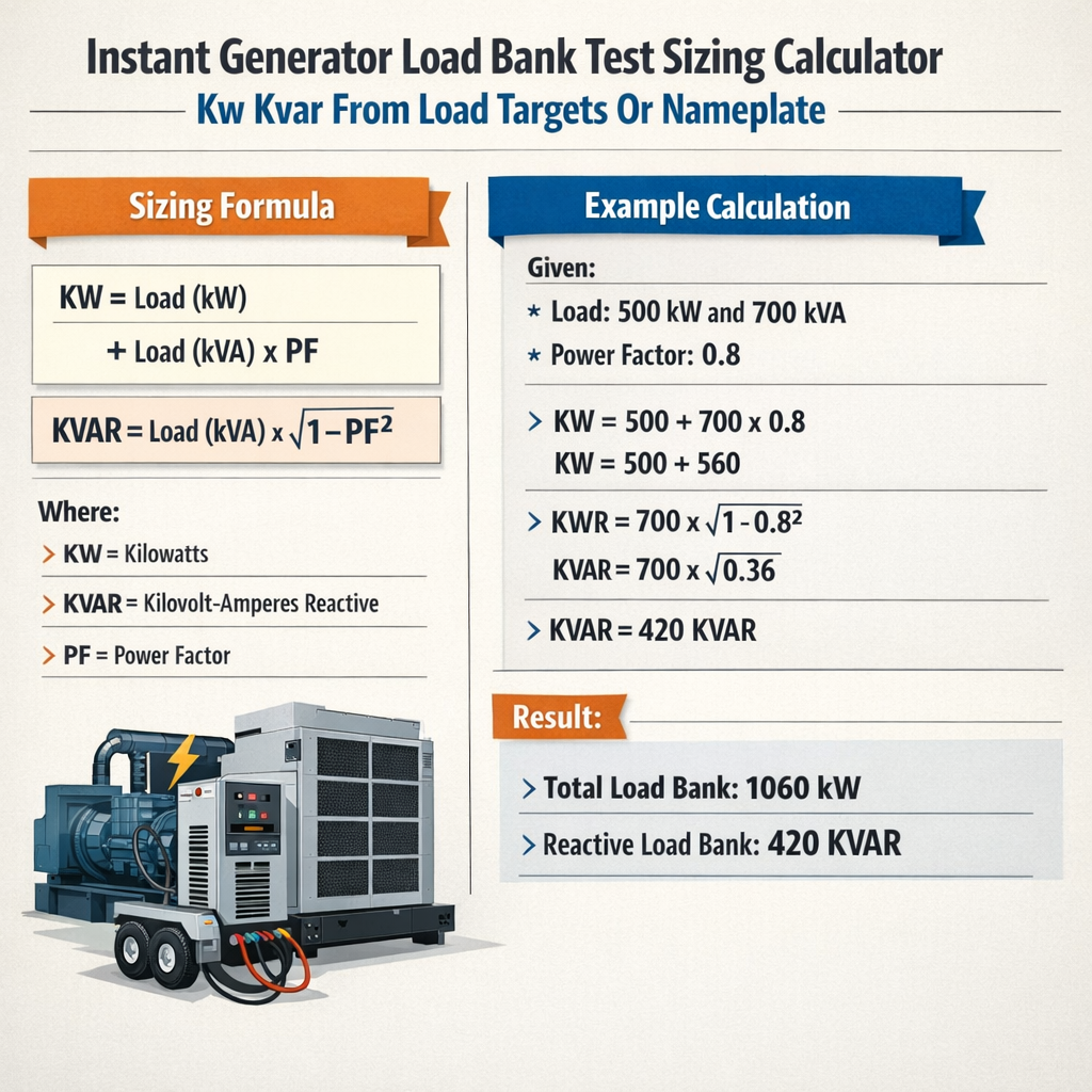
Instant Generator Load Bank Test Sizing — kW / kVAR from Load Targets or Nameplate
Scope and objectives for generator load bank sizing and instant calculators
This document describes analytical methods and a practical calculator workflow to determine instantaneous load bank sizing in kW and kVAR from either load targets or generator nameplate data. It is intended for electrical engineers, commissioning technicians, and test planners who must size resistive and reactive load elements to perform acceptance, maintenance, or proof tests on prime movers and alternators.
Key concepts and terminology
- kW — real power delivered to resistive loads, measured in kilowatts.
- kVAR — reactive power delivered or absorbed by inductive/capacitive elements, measured in kilovolt-amperes reactive.
- kVA — apparent power capacity of a generator; kVA = kW / PF.
- PF — power factor, cosine of load phase angle (lagging for inductive loads).
- Nameplate data — manufacturer-rated kVA and rated power factor used to compute rated kW.
- Load target — operational load expressed as kW or percentage of nameplate kW used for testing scenarios.
Fundamental formulas and variable definitions
All formulas below are expressed using plain HTML text characters. Each formula is followed by a variable explanation and typical values used in calculations.
1) Convert nameplate kVA to rated kW:
- kVA_nameplate: from generator nameplate (typical values: 50 kVA, 100 kVA, 500 kVA, 1000 kVA).
- PF_nameplate: typical rated PF = 0.8 or 0.8 lagging (common for standby), sometimes 0.9 or 1.0 for prime-rated machines.
2) Apparent power S for a given real power and PF:
- P: required test real power in kW.
- PF: target power factor for the test (typical values: 1.0, 0.9, 0.8).
3) Reactive power Q from P and PF:
- Q is given in kVAR; positive Q indicates inductive reactive demand (lagging).
- Use numeric examples after variable definitions.
4) Three-phase line current from real power:
- V_L-L: line-to-line voltage (typical values: 208 V, 400 V, 415 V, 480 V).
- sqrt(3) ≈ 1.732.
5) Three-phase line current from apparent power:
6) Percent loading relative to nameplate kW:
Design rules and practical constraints for instant load bank sizing
- Test kW requirement: Resistive load bank must be sized to provide the specified real power P_target. For example, a 400 kW resistive bank for 400 kW test.
- Reactive load requirement: If the test requires a specific PF or Q, provide either a reactive load bank or use synchronous machine methods. Reactive elements are specified in kVAR.
- Stepped vs continuously variable: Resistive banks are often modular and stepped; reactive banks can be tapped reactors or synchronous condensers for fine control.
- Voltage and current ratings: Ensure the load bank modules and connections are rated for the generator voltage and thermal duty of the test.
- Duty cycle and thermal management: Resistive banks generate heat; cooling and ventilation must be provided according to manufacturer guidance.
- Regulatory compliance: Test procedures must comply with NFPA 110, ISO 8528, and manufacturer recommended testing intervals.
Typical values and conversions
| kVA Nameplate | PF 0.8 → kW | PF 0.9 → kW | PF 1.0 → kW |
|---|---|---|---|
| 50 kVA | 40 kW | 45 kW | 50 kW |
| 100 kVA | 80 kW | 90 kW | 100 kW |
| 250 kVA | 200 kW | 225 kW | 250 kW |
| 500 kVA | 400 kW | 450 kW | 500 kW |
| 1000 kVA | 800 kW | 900 kW | 1000 kW |
| Voltage (L-L) | Current per kW at PF 1.0 (A/kW) | Current per kW at PF 0.8 (A/kW) | Examples: Current for 400 kW at PF 0.8 (A) |
|---|---|---|---|
| 208 V | 2.78 | 3.47 | 400 × 3.47 = 1388 A |
| 400 V | 1.44 | 1.80 | 400 × 1.80 = 720 A |
| 415 V | 1.39 | 1.74 | 400 × 1.74 = 696 A |
| 480 V | 1.20 | 1.50 | 400 × 1.50 = 600 A |
Using a calculator workflow: step-by-step procedure
To size a load bank instantly from either load targets or nameplate values, follow this workflow. Each step corresponds to the formulas above and yields the kW and kVAR equipment specification required.
- Obtain nameplate kVA and nameplate PF. Compute P_rated = kVA × PF. If only kW is specified, use that directly.
- Decide test target: either percent of rated kW (e.g., 30%, 50%, 100%) or a fixed kW value representing the expected load.
- Compute P_target (kW) = Load% × P_rated or use the fixed kW target.
- Select test PF_target for the test (e.g., 1.0 for resistive, 0.8 lagging for typical motor loads). Compute S_target = P_target / PF_target.
- Compute Q_target = sqrt(S_target^2 − P_target^2). This gives required kVAR for reactive bank sizing.
- Compute phase current using I = 1000 × P_target / (sqrt(3) × V × PF_target) or use S_target for apparent current. Verify generator and switchgear ratings.
- Specify load bank modules: choose resistive kW modules adding to P_target and reactive kVAR modules adding to Q_target. Include margin for control and meter accuracy.
Example formulas explained with typical numeric values
Take a 500 kVA generator rated at PF 0.8. Compute rated kW:
Typical test at 100% nameplate and PF 0.8:
If the generator voltage is 480 V, phase current for the test is:
Worked examples — full solutions
Example 1: Nameplate-based sizing for acceptance testing
Scenario: A site has a 750 kVA standby generator rated at PF 0.8. The commissioning specification requires a 100% load acceptance test at the nameplate power factor. Generator voltage is 480 V three-phase. Determine the resistive (kW) and reactive (kVAR) load bank sizes and the expected current per phase.
Step 1 — Compute rated kW:
Step 2 — Test target at 100%:
Step 3 — Apparent power:
Step 4 — Reactive power:
Step 5 — Line current per phase:
Specification result:
- Resistive bank requirement: 600 kW (modular arrangement e.g., 6 × 100 kW modules).
- Reactive bank requirement: 450 kVAR (choose tapped inductive reactors or synchronous reactive source).
- Expected line current: ~903 A per phase — ensure switchgear and cabling are rated and protective devices coordinated for continuous test duration.
Notes and practical adjustments:
- Allow ±5% margin to accommodate metering inaccuracies or module tolerances. Order slightly higher kW/kVAR bank capacity or ensure module combinations can be adjusted.
- If reactive modules are discrete, use nearest available bank size (for example 450 kVAR can be assembled from 3 × 150 kVAR modules).
- Consider power factor variation during transient loading; monitor and adjust slowly to avoid generator instability.
Example 2: Load-target-based sizing with mixed PF
Scenario: A facility has a variable critical load estimated at 250 kW with typical operating power factor 0.85 lagging. The installed generator nameplate is 400 kVA at PF 0.8 (P_rated = 320 kW). The commissioning team wants to run a load bank test representing the facility load concurrently with an additional resistive load to reach a 60% nameplate test. Determine required resistive and reactive bank sizes such that the combined loads emulate 250 kW facility at PF 0.85 plus added resistive load to reach total 60% of nameplate kW.
Step 1 — Compute nameplate rated kW:
Step 2 — Determine 60% nameplate target:
Step 3 — Facility load contribution is 250 kW at PF 0.85, but total test target is P_60 = 192 kW, which is less than facility load. So the realistic test scenario is to emulate the facility load alone and check generator capability; alternatively, simulate a reduced facility load. For this example we will emulate the facility load and verify whether generator can supply it.
Step 4 — Apparent power for facility load:
Step 5 — Reactive power for facility load:
Step 6 — Compare with generator capacity: Generator rated P_rated is 320 kW, S_rated = 400 kVA. The facility S_fac ≈ 294.12 kVA is within generator 400 kVA apparent capacity, and P_fac 250 kW is below rated 320 kW, so the generator can supply the load in steady state assuming thermal and installation conditions are satisfied.
Step 7 — If the objective is to load bank-test at 60% nameplate (192 kW) while simultaneously representing facility PF 0.85, one should reduce or shed facility load to achieve 192 kW. Alternatively, run the load bank to absorb excess kW while maintaining proper net PF. To emulate combined scenario where facility remains connected:
Required load bank resistive component P_bank = P_60 − P_fac_connected (if P_fac_connected < P_60). Here P_fac_connected = variable; if facility remains at 150 kW, then P_bank = 192 − 150 = 42 kW.
Example numeric: Suppose facility is operated at 150 kW @ PF 0.85 while test target remains 192 kW total.
S_total = P_total / PF_target — but composite PF must be computed from vector sum of individual S and Q elements.
Compute Q of facility (150 kW @ 0.85):
S_total = sqrt( P_total^2 + Q_total^2 ) = sqrt(192^2 + 93.17^2 ) ≈ sqrt(36864 + 8680) ≈ sqrt(45544) ≈ 213.4 kVA
Result: S_total 213.4 kVA is below generator 400 kVA capacity; the generator can supply combined test and facility. The composite PF = P_total / S_total = 192 / 213.4 ≈ 0.9 lagging.
Specification result for the testing team in this scenario:
- Resistive load bank modules required: 42 kW (choose modules allowing fine increments for control).
- No additional reactive bank required because composite PF remains acceptable, but confirm generator automatic voltage regulator (AVR) stability under these load dynamics.
- Verify transient overload capability and synchronizing elements if switching is involved.
Practical selection guidelines for load bank equipment
- Select resistive bank modules with appropriate voltage rating and thermal duty; confirm each module current does not exceed its busbar or connector rating.
- For reactive demands, choose inductive reactance or synchronous compensators rated for continuous operation during the test; ensure they are designed to produce lagging kVAR without overheating.
- Metering and control: use true RMS meters capable of measuring P, Q, S and PF to validate test targets and protect machines from instability.
- Control architecture: implement soft-start sequencing for multi-module banks to avoid large inrush currents and generator transient instability.
- Safety and ventilation: residual heat from resistive loads must be safely dissipated; follow manufacturer ventilation requirements and local codes.
| Common test target | Required resistive kW | Typical reactive kVAR @ PF 0.8 | Notes |
|---|---|---|---|
| 30% nameplate | 0.30 × P_rated | Compute Q from PF | Often used for light-load verification |
| 50% nameplate | 0.50 × P_rated | Compute Q from PF | Common maintenance load |
| 80% nameplate | 0.80 × P_rated | Compute Q from PF | Test for near-continuous operation |
| 100% nameplate | P_rated | Compute Q from PF | Acceptance and design verification |
Standards, references and authoritative guidance
Testing and sizing practices should be aligned with recognized standards and manufacturer instructions. Key references include:
- NFPA 110 — Standard for Emergency and Standby Power Systems. Link: https://www.nfpa.org/
- ISO 8528 — Reciprocating internal combustion engine driven alternating current generating sets. Link: https://www.iso.org/standard/70421.html
- IEEE standards and recommended practices for generator testing and system planning, including IEEE 446 (Emergency and standby power systems — recommended practice). Link: https://standards.ieee.org/
- Manufacturer technical manuals for specific generator sets and load bank equipment (e.g., Caterpillar, Cummins, Kohler).
- NETA and industry testing guides for electrical safety and acceptance testing. Link: https://www.netaworld.org/
Additional authoritative resources
- U.S. Department of Energy — Distributed Generation and CHP technologies: https://www.energy.gov/
- IEC 60034 — Rotating electrical machines for generator performance characteristics: https://www.iec.ch/
Verification, instrumentation and data capture during testing
Proper verification requires reliable metering for kW, kVAR, kVA, PF, voltage and frequency. Suggested instrumentation and practices:
- Install calibrated true-rms meters on each phase to record P, Q, S and PF contemporaneously.
- Record generator speed, cooling system temperature, oil pressure and exhaust temperature during the test.
- Log transient waveforms if possible to detect instability, voltage dips, or harmonic distortion that may affect generator behavior.
- Use stepwise loading and hold periods (e.g., 15 minutes per step) to allow thermal stabilization unless test requires prolonged operation per manufacturer guidance.
Common pitfalls and mitigation strategies
- Underestimating reactive demand — compute Q explicitly rather than assume PF. Reactive load mismatch can cause AVR and excitation instability.
- Insufficient cooling — resistive banks require ventilation proportional to heat flux. Confirm airflow and temperature rise limits.
- Protection coordination — ensure breakers and fuses are rated for test currents and do not trip, or plan staged tests to avoid nuisance trips.
- Harmonics — non-linear loads can introduce harmonics; use harmonic filters or measure THD to ensure generator ratings are not exceeded.
Summary of the calculator output fields for implementation
An instant generator load bank sizing calculator should produce the following outputs when given nameplate or target inputs:
- P_rated (kW) from nameplate kVA and PF
- P_target (kW) as percent or absolute value
- PF_target and computed S_target (kVA)
- Q_target (kVAR) required for reactive bank sizing
- Line current per phase at specified voltage
- Suggested modular bank configuration (module kW/kVAR sizes)
- Safety and control notes: ventilation, incremental loading schedule, metering recommendations
Practical recommendations for procurement and field implementation
- Specify modular load bank systems with incremental control and separate reactive modules when PF tests are required.
- Ensure vendor-provided documentation includes voltage, current, and continuous duty ratings for each module.
- Include spare capacity or modular expansion options to cover unexpected adjustments in test load or PF targets.
- Plan cable terminations and switchgear rated for expected test currents and include temporary busbars if necessary.
- Coordinate testing schedules with mechanical system cooldowns and safety officers for live testing in occupied facilities.
References
- NFPA. NFPA 110: Standard for Emergency and Standby Power Systems. National Fire Protection Association. https://www.nfpa.org/
- ISO. ISO 8528: Reciprocating internal combustion engine driven alternating current generating sets. https://www.iso.org/standard/70421.html
- IEEE. IEEE Standards and recommended practices for generator systems. https://standards.ieee.org/
- NETA. InterNational Electrical Testing Association resources for field testing. https://www.netaworld.org/
- Manufacturer guidance: Cummins Power Generation, Caterpillar Power Systems, Kohler Power Systems — consult specific generator manuals for detailed test intervals and limitations.
Final technical notes
- Always verify the specific generator nameplate, protective device ratings, and manufacturer-recommended test protocols before applying load bank configurations.
- Load bank sizing calculators must incorporate margin for instrumentation error, module tolerances, and environmental derating as applicable.
- When in doubt, consult the alternator manufacturer or a qualified testing contractor for custom reactive compensation strategies, including synchronous condenser options.