This tool determines PPE category based on NFPA 70E style input and arc flash calculations.
This article explains methodology, inputs, formulas, and examples for pragmatic PPE selection.
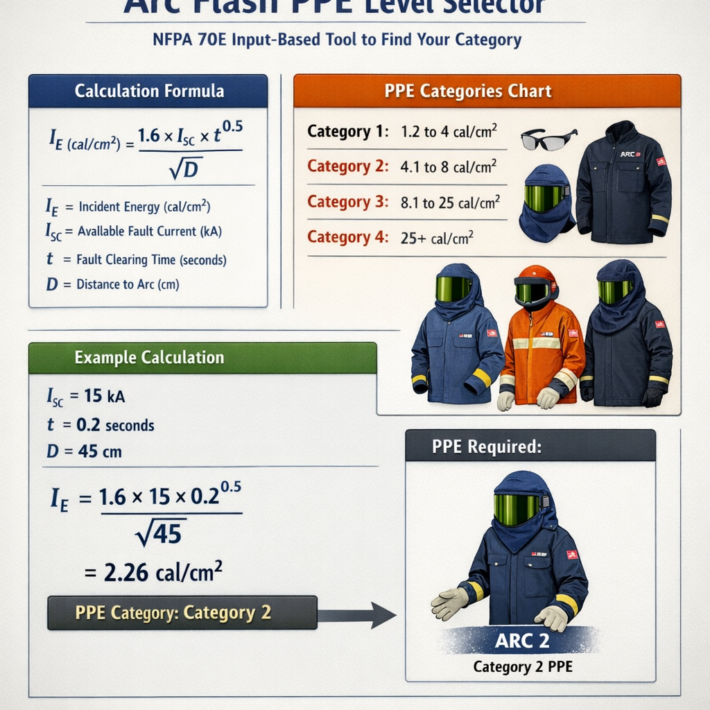
Arc Flash PPE Level Selector — Determine PPE Category from Incident Energy (NFPA 70E style)
Scope and operational concept of an NFPA 70E style PPE level selector
An Arc Flash PPE Level Selector converts site electrical parameters into a recommended protective clothing (PPE) requirement consistent with NFPA 70E principles. The selector uses systematic steps: determine available fault current, estimate arcing current, determine protective device clearing time, compute incident energy at worker distance, then select PPE whose ATPV (arc thermal performance value) equals or exceeds the incident energy. The tool must clearly flag assumptions, approximations and reference the applicable standards (NFPA 70E and IEEE 1584).Key functions expected from a professional selector:- Structured input capture for voltage, fault current, equipment geometry, protective device curves, working distance, conductor gap and enclosure type.
- Use of accepted empirical models (e.g., IEEE 1584) or calibrated simplified models where full IEEE computation is not available.
- Clear output: incident energy (cal/cm²) at working distance, boundary distance, recommended ATPV/PPE or hazard/risk category, and traceable calculation steps and assumptions.
- Audit trail and links to normative references for compliance.
Required inputs and why each matters
Essential electrical inputs
- System nominal voltage (V) — influences arc formation and arcing current behavior.
- Available bolted fault current (Ibf, kA) — initial drive for arc current estimation.
- Protective device type and time-current characteristic — determines arc duration (t).
- System grounding and source impedance data — impacts arcing current magnitude.
Equipment geometry and human factors
- Working distance (D) — distance from arc to worker’s torso/face; incident energy decays with distance.
- Enclosure type and size (e.g., open rack, bucket, cubicle) and conductor gap — change the empirical constants used to derive arc current and energy.
- PPE ensemble baseline and layering — used to verify ATPV adequacy when comparing against incident energy.
Core calculation workflow (algorithm)
1. Validate inputs and determine whether a full IEEE 1584 calculation is feasible (all parameters available). 2. Compute arcing current (Ia) using IEEE 1584 empirical relationships or a validated approximation function Ia = f(Ibf, V, gap, enclosure). 3. Determine arc duration (t) from protective device characteristics (time-current curve or trip characteristics). For devices that clear on upstream settings, compute the actual clearing time at estimated Ia. 4. Compute incident energy (E) at working distance (D) using an empirical incident energy model derived from IEEE 1584 or a calibrated simplified formula. 5. Choose PPE: select garment ensemble with ATPV >= E or use NFPA 70E historical PPE categories mapping only if organizational policy requires category-style labeling. Provide required PPE items for each category or energy level. 6. Provide safety boundaries (arc flash boundary) and documentation for label generation.Generic empirical formulas (symbolic)
Arcing current (Ia) = f(Ibf, V, gap, enclosure) — empirical model dependent upon electrode gap and enclosure geometry.
Incident energy (E) = K × Ia^α × t / D^β
Arc flash boundary distance (R_boundary) is the distance at which an unprotected worker would receive 1.2 cal/cm² (typical threshold for second-degree burn):
R_boundary = D × sqrt(E / 1.2)
Explanation of variables and typical values
- Ia — arcing fault current, in kA. Typical low-voltage values: 6–30 kA. Typical medium-voltage open-air arcs: 10–50 kA depending on system.
- Ibf — bolted fault current, kA. Typical plant maximum available fault currents: 5–50 kA.
- V — nominal system voltage (single or three-phase), volts (V). Examples: 208 V, 480 V, 4.16 kV.
- t — arc duration (seconds). Typical protective device clearing times: fuses 0.03–0.5 s depending on size and curve; breakers 0.05–0.5 s depending on settings and fault magnitude.
- D — working distance (m). Typical working distances: 0.305 m (12 in), 0.457 m (18 in), 0.762 m (30 in).
- K, α, β — empirical constants. For IEEE 1584-derived approximations K might be on order of 0.1–1.0 (unit conversion included); α commonly around 1.0–1.6; β commonly near 2.0 (inverse-square distance dependence). Values must be calibrated to IEEE 1584 curves or validated laboratory data when possible.
- E — incident energy, in cal/cm².
Mapping incident energy to PPE — typical organizational practice
Many organizations historically used NFPA 70E Hazard/Risk Categories (HRC) 0–4 with representative ATPV ensemble ratings. Since NFPA 70E (2015/2018) encourages using calculated incident energy compared against garment ATPV, organizations still often present a category-style mapping for operational simplicity.| Historical HRC / Category | Representative minimum ATPV (cal/cm²) | Typical ensemble examples |
|---|---|---|
| 0 | <4 | Daily clothing + arc-rated face shield (where required); no arc-rated outer garment |
| 1 | 4 | Arc-rated shirt + pants or coverall, arc-rated face protection, gloves as needed |
| 2 | 8 | Arc-rated coverall or jacket + pants, arc-rated hood or face shield, gloves |
| 3 | 25 | Heavier arc-rated suit or layering, arc-rated hood, insulated gloves with leather protectors |
| 4 | 40 | Full arc-rated suit ensembles, arc-rated hood, insulating gloves and leather protectors |
Extensive typical value tables for quick reference
| Parameter | Typical range | Notes |
|---|---|---|
| Working distance (D) | 0.305–0.762 m (12–30 in) | Use the distance stipulated for the exposed body part (torso/face). Label should specify measured working distance. |
| Bolted fault current (Ibf) | 5–50 kA (industrial facilities) | Plant design or utility short-circuit study provides accurate values. |
| Arc duration (t) | 0.03–0.5 s | Depends heavily on protective device type and coordination. Use device curves and measured clearing times at estimated Ia. |
| Typical arcing current (Ia) | 5–35 kA (low-voltage) | Arcing current usually less than bolted fault current; actual Ia must be computed or estimated per standard. |
| Common ATPV garment ratings | 4, 8, 25, 40 cal/cm² | Manufacturers publish ATPV for specific garments. |
| Arc flash boundary (1.2 cal/cm²) | 0.5–5.0 m depending on severity | Computed per incident energy model; necessary for access control and safe standoff. |
Worked examples — practical, step-by-step cases
Note: The calculations below use a simplified incident energy approximation for demonstration and training purposes only. They are not a substitute for a full IEEE 1584-based calculation or vendor certified arc flash study. When in doubt, use a certified arc flash calculation tool or an electrical engineer specialized in arc flash analysis.Example 1 — Low-voltage distribution panel, 480 V three-phase
Scenario inputs:- System voltage: 480 V three-phase
- Available bolted fault current (Ibf): 25 kA
- Estimated arcing current (Ia) for enclosed panel (approximation from typical models): 14 kA
- Protective device: molded-case breaker with expected clearing time t: 0.1 s at Ia
- Working distance (D): 0.457 m (18 in)
- Simplified empirical coefficient selected for demonstration: K = 0.5, α = 1.5, β = 2.0
E = K × Ia^α × t / D^β
- Ia^α = 14^1.5 = 14 × sqrt(14) ≈ 14 × 3.7417 = 52.3838
- Numerator = K × Ia^α × t = 0.5 × 52.3838 × 0.1 = 2.61919
- D^β = 0.457^2 = 0.20865
- E = 2.61919 / 0.20865 ≈ 12.55 cal/cm²
- Calculated incident energy: 12.55 cal/cm²
- Minimum ATPV requirement: choose garment ATPV >= 12.55 cal/cm²
- Typical available garment ATPV choices: 8 cal/cm² (insufficient), 25 cal/cm² (sufficient)
- Recommended ensemble: ATPV 25 cal/cm² garment ensemble (historic HRC 3 mapping), arc-rated hood, arc-rated gloves rated above the incident energy, leather protectors as required, and face protection.
R_boundary = D × sqrt(E / 1.2)
- sqrt(E/1.2) = sqrt(12.55 / 1.2) = sqrt(10.458) = 3.233
- R_boundary = 0.457 m × 3.233 = 1.478 m (≈58.2 inches)
- Incident energy ≈ 12.6 cal/cm² at 18 in
- Recommended ATPV: ≥ 25 cal/cm² ensemble
- Arc flash boundary ≈ 1.48 m (58 in)
- Document assumptions: Ia estimated, K and exponents representative for demo, use IEEE 1584 for definitive numbers
Example 2 — Medium-voltage switchgear, 4.16 kV bus
Scenario inputs:- System voltage: 4.16 kV three-phase
- Available bolted fault current (Ibf): 12 kA
- Estimated arcing current (Ia) from an IEEE 1584 approximate lookup for enclosed switchgear: 8.5 kA
- Protective device: upstream relay + circuit breaker expected clearing time t: 0.07 s
- Working distance (D): 0.762 m (30 in)
- Simplified empirical coefficient for demonstration: K = 0.75, α = 1.4, β = 2.0
E = K × Ia^α × t / D^β
- Ia^α = 8.5^1.4 — compute by exponent: ln(8.5)=2.140, ×1.4=2.996, exp(2.996)=20.012 (approx)
- Numerator = 0.75 × 20.012 × 0.07 = 1.0506
- D^2 = 0.762^2 = 0.5806
- E = 1.0506 / 0.5806 = 1.809 cal/cm²
- Calculated incident energy: ≈ 1.81 cal/cm²
- Minimum ATPV required: ≥ 1.81 cal/cm²
- Typical garments: 4 cal/cm² garments readily available (HRC 1 mapping), 8 cal/cm² optional for margin
- Recommended ensemble: ATPV 4 cal/cm² arc-rated shirt/pants or coverall, plus arc-rated face/eye protection; gloves if hand exposure anticipated.
R_boundary = D × sqrt(E / 1.2)
- sqrt(1.809 / 1.2) = sqrt(1.5075) = 1.2278
- R_boundary = 0.762 × 1.2278 = 0.935 m (≈36.8 in)
- Incident energy ≈ 1.81 cal/cm² at 30 in
- Recommended ATPV: ≥ 4 cal/cm² ensemble (for margin over 1.81)
- Arc flash boundary ≈ 0.94 m (37 in)
- Assumptions: empirical K and exponent selection for demo; use full IEEE 1584 for final compliance labeling
Best practices for implementing a PPE level selector tool
Data governance and traceability
- Maintain input provenance (fault studies, utility data, site measurements) and stamp each calculation with assumptions and model version (e.g., IEEE 1584-2018).
- Store device curves and calculation snapshots for audit and regulatory review.
Usability and operator safety features
- Require mandatory fields (working distance, available fault current, device clearing time) and prevent silent defaults that hide uncertainty.
- Produce clear labels: incident energy, working distance, arc flash boundary, recommended ATPV and PPE list, and date/version of the study.
Validation and calibration
- Validate simplified models against full IEEE 1584-calculations in representative scenarios. Keep validation reports.
- Where differences exceed organizational tolerance, require full-calculation path (IEEE 1584) rather than simplified model.
Regulatory and standard references (authoritative links)
- NFPA 70E: Standard for Electrical Safety in the Workplace — official NFPA resource and documentation: https://www.nfpa.org/70E (and code detail: https://www.nfpa.org/codes-and-standards/all-codes-and-standards/list-of-codes-and-standards/detail?code=70E)
- IEEE 1584 — Guide for Performing Arc-Flash Hazard Calculations (2018 revision): https://standards.ieee.org/standard/1584-2018.html
- OSHA general electrical safety guidance: https://www.osha.gov/electrical
- ANSI/ASTM arc rating and testing information (NFPA-referenced garments): consult manufacturers and laboratory test reports for ATPV certification details.
Common caveats and limitations
- Simplified formulae and coefficients are for demonstration or conservative screening only. Use IEEE 1584 or validated vendor software for final labeling and compliance.
- ATPV certification applies only to specific garments as tested by manufacturers; selecting a garment requires verifying the ATPV value on manufacturer documentation.
- Device clearing times vary with actual fault magnitude and coordination settings; always use device curves or recorded clearing times where possible.
Implementation checklist for an NFPA 70E style selector tool
- Define required inputs with mandatory validation and unit checks (V, kA, seconds, meters/inches).
- Allow selection of calculation mode: full IEEE 1584 vs. simplified/organizational model.
- Include a library of device time-current curves and a method to compute clearing time at the estimated arcing current.
- Include garment ATPV database with manufacturer certificates and allow matching ATPV to incident energy automatically.
- Output a printable label template containing incident energy, working distance, arc flash boundary, recommended PPE, date of study, and calculation model version.
- Log inputs, outputs, and assumptions for audit purposes.