This article explains methods for generator load bank test sizing and calculating kW and kVAR.
Scope covers calculating kW and kVAR from load or nameplate for correct load bank selection.
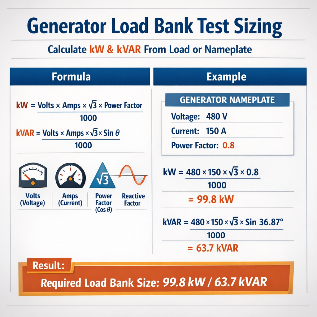
Generator Load Bank Test Sizing — Calculate kW and kVAR from Load or Nameplate
Fundamental electrical relationships for generator test sizing
Accurate generator load bank test sizing depends on converting available nameplate data or measured load into kilowatts (kW), kilovolt-amperes reactive (kVAR) and kilovolt-amperes (kVA). The most common formulas used in field engineering for three-phase and single-phase systems are presented below. Variables are defined and typical values supplied to enable practical application.
Core formula set for three-phase balanced systems
Use these formulas for balanced three-phase synchronous generator analysis:
- V_LL = Line-to-line RMS voltage in volts (typical: 400 V, 480 V, 600 V).
- I_L = Line current in amperes measured or nameplate rated.
- PF = Power factor (unitless, typical: 0.8 lagging for motor loads, 1.0 for resistive).
- √3 = 1.732 (mathematical constant for three-phase conversion).
Single-phase formulas
For single-phase loads:
- V = RMS voltage between conductors (typical: 120 V, 230 V).
- I = Current in amperes.
Interpreting nameplate data and converting to test loads
Nameplate information can be incomplete: manufacturers often show rated kVA, rated kW at specific PF, rated current, or only voltage and current. Use the conversion formulas above to derive the missing quantities.
Common nameplate scenarios and conversion rules
- If kVA and PF are given: kW = kVA × PF.
- If rated current and voltage are given for three-phase: compute kVA with kVA = (V_LL × I_L × 1.732) / 1000, then kW = kVA × PF.
- If only kW is given: kVA = kW / PF (use specified or assumed PF).
- If only current is given for each phase on a three-phase generator: compute electrical power from measured voltage and PF.
Typical values and conversion tables
Below are extensive tables with common generator voltages, currents, and simplified conversions that are frequently used during field sizing and pre-test calculations.
| Voltage (V LL) | Rated Current (A) | Calculated kVA (3φ) | kW @ PF 0.8 | kW @ PF 0.9 |
|---|---|---|---|---|
| 208 | 100 | 35.97 | 28.78 | 32.37 |
| 400 | 100 | 69.28 | 55.42 | 62.35 |
| 480 | 100 | 83.14 | 66.51 | 74.83 |
| 600 | 100 | 103.92 | 83.14 | 93.53 |
| 480 | 200 | 166.28 | 133.02 | 149.64 |
| 480 | 400 | 332.55 | 266.04 | 299.30 |
Notes: kVA (3φ) = V_LL × I_L × 1.732 / 1000. Values are rounded to two decimals. These tables help quickly estimate generator capability from nameplate current.
Reactive loading and the need for kVAR-capable load banks
Resistive load banks absorb kW but do not absorb kVAR. If the objective of the test is to validate generator voltage regulation, excitation system response, AVR stability, or to simulate motor-dominant loads, a reactive load bank or a combination resistive/inductive bank is required. Reactive test sets typically include inductive elements, reactor banks, or controllable power electronics.
Calculating kVAR from power factor or phase angle
Given kW and PF, compute kVAR by first determining kVA:
- Example typical PF values: 0.95 (lighting and resistive-heavy), 0.85 (mixed loads), 0.8 or 0.7 (motor heavy).
- If PF < 0.7, verify motor inrush and starting currents when testing.
Derating factors and environmental corrections
Generator nameplate ratings assume specific ambient conditions and altitude. Correct test sizing must include derating for ambient temperature, altitude, fuel quality, and long-term continuous loads. Use manufacturer derating tables and recognized standards to apply correct multipliers.
Common derating considerations
- Altitude: above 1000 m (3280 ft) derate roughly 3% per 300 m (1000 ft) depending on manufacturer.
- Ambient temperature: many sets rated at 25 °C; increase ambient reduces cooling capacity and output.
- Fuel type and quality: gaseous fuel installations often require mixture corrections.
- Continuous vs standby duty: continuous ratings typically lower than standby; select load bank size accordingly.
| Condition | Typical Correction | Application |
|---|---|---|
| Altitude 1000 m | −3% (approx.) | High-elevation sites |
| Altitude 2000 m | −6% (approx.) | Mountain installations |
| Ambient 35 °C | −2% to −5% (manufacturer dependent) | Hot climates |
| Continuous duty factor | Use continuous rating (often 80–90% of standby) | Permanent loads |
Step-by-step calculation workflow for load bank sizing
- Collect generator nameplate and control documentation: rated kW, kVA, rated current, rated voltage, PF, continuous/standby category.
- Inventory connected loads or simulate expected load profile for test: motors, VFDs, resistive loads, transformers, inrush characteristics.
- Compute total kW and kVAR using the formulas in the previous section for each load grouping.
- Apply derating factors for altitude, ambient, and continuous duty.
- Decide test objectives: full nameplate kW verification, endurance test, block loading for stepwise testing, or reactive performance validation.
- Select load bank type: resistive (kW only), resistive+inductive (kW+kVAR), or electronically controlled (adjustable PF).
- Specify load bank capacity and module granularity considering generator protective device coordination and ramp rates.
- Document and plan safety, grounding, and switching arrangements for test execution.
Example 1 — Three-phase generator using nameplate values (detailed)
Scenario: A standby diesel generator nameplate shows 480 V line-to-line, rated current 375 A, rated kVA 249.7, rated power at PF 0.8 is 199.8 kW. Objective: size a load bank for a 100% nameplate acceptance test and determine kVAR required for PF 0.8.
Step 2: If only voltage and current were provided, recompute kVA:
Note: The computed kVA (311.76 kVA) differs from nameplate kVA (249.7 kVA). This indicates the nameplate current 375 A might be the maximum current under a different voltage or that the generator has multiple ratings. Always use the manufacturer’s specified kVA/kW for test sizing. For this example we will use the official nameplate kVA = 249.7 kVA.
Step 3: Calculate kVAR required to present a PF of 0.8 lagging during the test.
Step 4: Load bank selection.
- Required resistive load = kW = 199.76 kW (round to 200 kW resistive capacity).
- Required reactive capability = 149.82 kVAR inductive to obtain PF 0.8.
- Select a load bank system that supports at least 200 kW resistive and 150 kVAR reactive (e.g., modular R + L bank or electronic PF control).
Step 5: Consider safety margin and derating. If altitude requires −3% derate then test kW target = 200 kW × 0.97 = 194 kW. Adjust load bank module selection to ensure modular steps allow reaching this value accurately while not exceeding generator thermal limits.
Final recommendation: Use a 250 kW resistive / 200 kVAR modular reactive bank with step increments enabling 5–10% resolution. Confirm generator manufacturer acceptance testing procedures before execution.
Example 2 — Mixed load derived from measured currents (detailed)
Scenario: Field measurement on a three-phase bus shows phase currents: A = 150 A, B = 140 A, C = 160 A at 400 V line-to-line. Loads are motor-dominant; measured system PF (meter) = 0.78 lagging. Objective: determine total kW and kVAR and size a load bank for a 90% load test to verify continuous performance.
Step 1: Determine average line current for balanced-equivalent analysis or compute per-phase power if the system is unbalanced. For conservative sizing, use the maximum phase current to ensure worst-case capacity:
Use I_max = 160 A for approximate calculation (alternatively perform three-phase unbalanced power calculation).
Step 4: Compute kVAR:
Step 5: Apply test target at 90% of measured load for endurance verification:
Step 6: Load bank selection and configuration:
- Resistive capacity required = 78 kW (round to 80 kW module availability).
- Reactive capability required = 63 kVAR (round to 70 kVAR reactive module or use electronic PF control).
- Because actual system is unbalanced, plan to measure each phase during the test and install load bank connection to ensure no single-phase overload occurs. Use a three-phase load bank with adjustable module distribution across phases or use balancing transformers.
Step 7: Safety and coordination: verify generator protective relays, thermal limits, and cooling capacity for prolonged 90% operation. Record pre- and post-test speeds, temperatures, and fuel consumption to validate manufacturer continuous ratings.
Motor starting and transient considerations
Large motor starts can impose severe transient kVA demands well in excess of steady-state nameplate ratings. When sizing a load bank and planning tests, account for the following:
- Locked-rotor current (LRA) can be 4–8 times rated current for induction motors; coordinate with generator transient capability and AVR response.
- Momentary voltage dip tolerance: generator excitation and AVR must be validated under motor starts. Reactive load banks with step control can emulate motor-like PF and transient behavior.
- Staged motor starting or soft-starters should be used when on-site loads will be started during generator operation to protect generator and switchgear.
Load bank module selection, control and step granularity
Load banks are typically modular to allow stepwise loading and controlled ramp rates. Key specification parameters include unit kW per module, total resistive kW, reactive kVAR modules, step resolution, step switching type (contactors vs. thyristors), and control interfaces (manual, remote PLC, Ethernet).
| Module Size (kW) | Advantages | Recommended Application |
|---|---|---|
| 5 kW | Fine resolution, precise control | Commissioning small generators, fine-tune PF |
| 10–25 kW | Good compromise resolution and logistics | Most field tests 50–500 kW |
| 50–100 kW | Efficient for large tests, fewer modules | Utility-scale or rental for large gensets |
| kVAR modules | Inductive/reactive simulation | PF testing, motor-like load emulation |
Testing practices and measurement instrumentation
Accurate metering is essential. Use calibrated three-phase power analyzers to log voltage, current, kW, kVAR, kVA, PF, frequency, and harmonic distortion. Record thermal parameters, exhaust temperatures, oil pressure, fuel consumption, and bearing temperatures in endurance tests.
- Ensure power analyzer accuracy class (Class 0.5 or better) for acceptance testing.
- Use synchronized logging to correlate electrical events with engine control alarms.
- Record at minimum 1-second intervals for transient analysis during motor starts or step changes.
Regulatory and normative references
Follow national and international standards when planning generator acceptance tests and load bank sizing. Relevant references include:
- NFPA 110: Standard for Emergency and Standby Power Systems — provides performance testing and acceptance criteria. See: https://www.nfpa.org
- IEEE Std 446 (Emer-PWR Guide): Recommended Practice for Emergency and Standby Power Systems for Industrial and Commercial Applications — guidance on system design and testing. See: https://standards.ieee.org
- IEC 60034: Rotating electrical machines — applicable for generator testing, performance, and thermal limits. See: https://www.iec.ch
- NEMA MG 1: Motors and Generators — mechanical and electrical characteristics relevant for starting and loading. See: https://www.nema.org
- ISO 8528: Reciprocating internal combustion engine driven alternating current generating sets — includes performance and testing recommendations. See: https://www.iso.org
Troubleshooting common discrepancies between nameplate and measured values
When field measurements differ from nameplate expectations, common causes and checks include:
- Voltage mismatch: confirm actual measured V_LL vs nameplate rating.
- Incorrect PF assumption: measure PF under representative load; nameplate PF may be different or only for standby.
- Generator control settings: governor limits, overload protection, or current limiting may prevent reaching nameplate kW.
- Derating conditions: altitude and ambient temperature may reduce available output.
- Instrumentation error: verify calibration of current transformers, voltage probes, and power analyzers.
Recommended diagnostic steps
- Verify wiring and CT/VTs are correctly rated and phase-oriented.
- Perform a no-load and incremental load test while logging parameters to identify where power meets limits.
- Consult the generator manufacturer for engine governor and alternator excitation settings if voltage or frequency regulation is unstable under load.
Operational planning and safety checklist for on-site load bank testing
Before performing any load bank test, validate the following items to ensure personnel safety and equipment protection:
- Proper grounding of load bank and generator frame.
- Isolation switches and interlocks to prevent backfeeding or paralleling errors.
- Fire suppression and fuel isolation plans for endurance tests.
- Clear communication protocols and emergency shutdown procedures.
- Permit and access control as required by site regulations and local authorities.
Practical selection examples and vendor considerations
When procuring or renting a load bank, specify the following to vendors to ensure correct sizing and capability:
- Required kW resistive capacity and kVAR reactive capacity.
- Step resolution and module sizes.
- Connection scheme (delta/wye, neutral availability, single-phase vs three-phase).
- Switchgear, cabling, and generator adaptors rated for expected currents and voltages.
- Control interface preferences (manual, automatic sequencing, remote PLC/Ethernet).
| Requirement | Specification Example | Rationale |
|---|---|---|
| Resistive kW | 200 kW | Match or exceed generator nameplate kW for acceptance testing |
| Reactive kVAR | 150 kVAR | Required to test PF 0.8 and AVR response |
| Module size | 10 kW steps | Good balance between resolution and logistics |
| Control | Remote PLC with Ethernet logging | Automated sequences and data capture for reports |
Data reporting and acceptance criteria
Acceptance test reports should include logged traces and summarized values for the following parameters at each test step:
- kW, kVAR, kVA, PF
- Voltage and frequency
- Engine coolant and oil temperatures, oil pressure
- Fuel consumption rate
- No-load and loaded sound levels if specified
- Deviations from nameplate and any trip events with timestamps
Acceptance criteria typically require the generator to sustain rated output without protective trips and maintain voltage and frequency within specified tolerances per NFPA 110 and manufacturer recommendations.
Summary of practical calculation checklist
- Collect nameplate and measured data: Voltage, Current, kVA, kW, PF.
- Use kVA = (V × I × √3)/1000 for three-phase; kW = kVA × PF.
- Compute kVAR from kVA and kW using kVAR = sqrt(kVA² − kW²).
- Apply derating for altitude, ambient, and duty cycle.
- Select resistive and reactive load bank capacity with appropriate module granularity.
- Plan for motor starting and transient requirements if applicable.
- Document instrumentation, interlocks, and safety procedures.
Further reading and authoritative resources
Consult the following authoritative sources for detailed performance curves, derating tables, and test procedures:
- NFPA 110 — Standard for Emergency and Standby Power Systems: https://www.nfpa.org/codes-and-standards/all-codes-and-standards/list-of-codes-and-standards/detail?code=110
- IEEE Std 446 — IEEE Recommended Practice for Emergency and Standby Power Systems: https://standards.ieee.org/standard/446-1995.html
- IEC 60034 series — Rotating electrical machines: https://www.iec.ch/
- ISO 8528 — Reciprocating internal combustion engine driven AC generating sets: https://www.iso.org/standard/11830.html
- NEMA MG 1 — Motors and Generators: https://www.nema.org/standards
Adhering to these formulas, workflows, and standards ensures repeatable, auditable load bank testing and correct generator sizing for commissioning, acceptance, and reliability verification.