Receptacle load calculators speed design decisions, ensuring breaker selection, conductor sizing, and code compliance adherence.
This article compares general purpose versus dedicated circuit totals, providing practical workflows and verification examples.Receptacle Load Calculator – General-Purpose vs Dedicated Circuit Design Totals
Fundamental concepts for receptacle load calculation
Accurate receptacle load calculation reduces overdesign, meets regulations, and avoids nuisance trips. Two primary calculation modes are used by engineers and electricians:
- General-purpose (multiple receptacles on a branch circuit) — uses demand or per-receptacle VA assumptions for sizing.
- Dedicated (single load or appliance per circuit) — sized to the specific connected equipment actual and continuous loads.
Key regulatory and engineering constraints
- Continuous load rule: loads expected to run more than three hours must be treated as continuous; conductor and overcurrent protection sizing consider 125% of continuous current.
- Diversity and demand factors: codes allow applying standard VA per receptacle or per area rather than the sum of nameplate ratings to avoid conservative oversizing.
- Voltage system considerations: typical voltages are 120/240V split-phase (North America) and 230V single-phase (international). Calculations differ only by the applied voltage and distribution method.
Essential formulas (HTML-only presentation)
Where:
- P = total power in watts (W)
- V = nominal voltage in volts (V) (e.g., 120, 230)
- I = current in amperes (A)
- I_load = P / V
- I_breaker is the minimum breaker size to protect a continuous load
- S = apparent power in volt-amperes (VA)
- V_line = line-to-line voltage (e.g., 400 V)
- √3 ≈ 1.732
Typical nominal voltages used in worked examples:
- North America dwelling circuits: V = 120 V (single branch receptacle)
- International single-phase circuits: V = 230 V
Code references and normative background
Always verify calculations against the applicable national/local wiring regulations. Key international references include:
- National Fire Protection Association (NFPA) — NFPA 70, National Electrical Code (NEC). Relevant articles: 210 (branch circuits), 220 (load calculations), and 422 (appliances). See https://www.nfpa.org/nec
- International Electrotechnical Commission — IEC 60364 series for electrical installations (general requirements and design). See https://www.iec.ch
- Institution of Engineering and Technology (IET) Wiring Regulations — BS 7671 for the UK. See https://www.theiet.org/
- Electrical Safety Foundation International (ESFI) and Canadian Electrical Code (for Canadian jurisdiction-specific guidance).
NEC-specific practice commonly used in the United States:
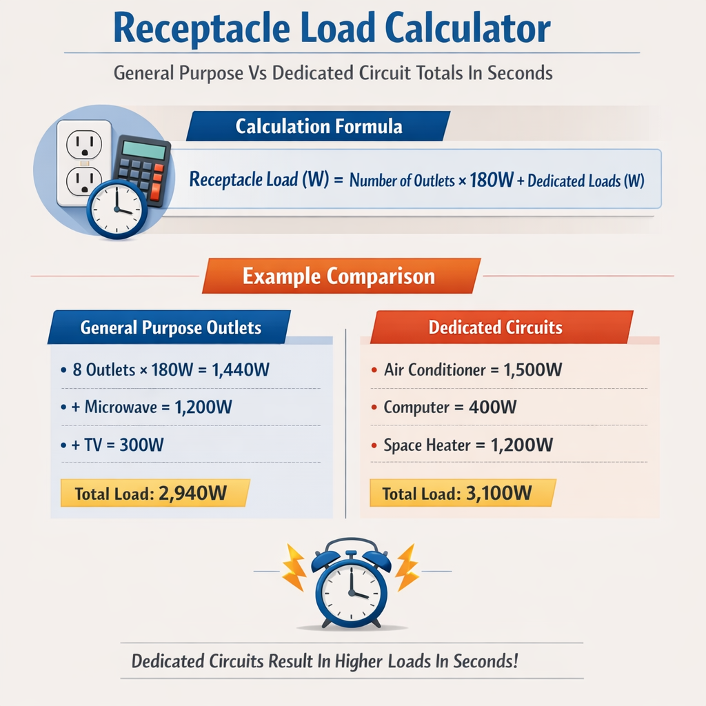
- NEC 220.14(I) (historically) and 210.5 guidance: use 180 VA per general-purpose receptacle for dwelling-unit branch-circuit calculations (verify latest edition for precise citations and local amendments).
- NEC 210.52 prescribes required receptacle placement and small-appliance branch circuit rules for kitchens.
General-purpose circuits: methodology and typical VA allowances
General-purpose circuits serve multiple receptacles in living areas, bedrooms, or offices. Instead of summing nameplate wattages, designers commonly use per-receptacle VA allowances and demand factors allowed by code.
Common per-receptacle allowance (practical engineering rule)
For dwelling units, a widely accepted engineering convention is:
- Use 180 VA per general-purpose receptacle for sizing dwelling branch-circuits and load aggregation (verify against local code edition).
| Receptacles per branch | Total VA (180 VA each) | Current @120 V (A) | Recommended minimum breaker size |
|---|---|---|---|
| 2 | 360 VA | 3.0 A | 15 A |
| 4 | 720 VA | 6.0 A | 15 A |
| 6 | 1,080 VA | 9.0 A | 15 A |
| 8 | 1,440 VA | 12.0 A | 15 A |
| 10 | 1,800 VA | 15.0 A | 20 A |
| 12 | 2,160 VA | 18.0 A | 20 A |
| 16 | 2,880 VA | 24.0 A | 30 A |
| 20 | 3,600 VA | 30.0 A | 40 A (change branch configuration) |
Notes:
- At 120 V, a 15 A circuit can reasonably supply up to 1,800 VA (15 A × 120 V = 1,800 VA) but continuous-load rules apply.
- For continuous loads, apply the 125% multiplier to determine minimum breaker and conductor ampacity.
Area and square footage approaches (commercial or mixed use)
In non-dwelling occupancies, codes often prescribe lighting and receptacle loads per square foot (or square meter) with demand factors. For example, electrical design may use:
- Office/commercial: a lighting/receptacle combined load using the code-specified VA/ft² and associated demand factors (refer to NEC Article 220 or your local code).
| Occupancy type | Common design approach | Typical VA density (indicative) |
|---|---|---|
| Office | VA/ft² method with demand factors | 3–5 VA/ft² (lighting only) + receptacle allowances per NEC |
| Retail | Combined lighting and receptacle VA/ft² | 3.5–6 VA/ft² |
| Workshop/Industrial | Sum motor and receptacle loads with dedicated circuits | Varies widely; equipment-specific |
Dedicated circuits: appliance-specific sizing and rules
Dedicated circuits supply single appliances or specific equipment and must be sized using the actual connected load and continuous-load rules. Examples include electric ranges, dryers, water heaters, HVAC equipment, and high-power motors.
Typical appliance loads and recommended circuit sizing
| Appliance | Typical power (W) | Voltage | Calculated current (A) | Recommended breaker/conductor |
|---|---|---|---|---|
| Refrigerator (residential) | 600–800 W | 120 V | 5–6.7 A | 15 A branch (often shared or dedicated depending on code) |
| Microwave (countertop) | 800–1,500 W | 120 V | 6.7–12.5 A | 20 A (often dedicated for built-in units) |
| Garbage disposal | 500–1,250 W | 120 V | 4.2–10.4 A | 15–20 A |
| Dishwasher | 1,200–1,800 W | 120 V | 10–15 A | 15–20 A dedicated or on small-appliance circuit per code |
| Electric clothes dryer | 3,800–5,000 W | 240 V | 15.8–20.8 A | 30 A 240 V dedicated circuit |
| Electric range | 8,000–12,000 W | 240 V | 33–50 A | 40–50 A dedicated circuit |
| Water heater (tank) | 3,000–4,500 W | 240 V | 12.5–18.8 A | 30 A dedicated circuit usually |
These values are typical engineering guidance. Always use appliance nameplate data for final sizing and check local code rules for required dedicated circuits.
Step-by-step workflows for fast totals in seconds
Use this checklist to calculate totals quickly and defensibly:
- Identify each receptacle, classification (general vs appliance), and location (kitchen, living, office).
- Assign VA per receptacle for general-purpose circuits (e.g., 180 VA per receptacle in dwelling units) or use nameplate ratings for dedicated circuits.
- Sum VA by branch or feeder grouping.
- Compute current: I = P / V.
- Apply continuous-load multiplier if applicable: breaker minimum = I × 1.25.
- Select standard breaker size and conductor ampacity. Verify voltage drop and temperature correction factors as required.
Checks and validation
- Confirm compliance with required dedicated circuits per local code (e.g., kitchen small-appliance circuits).
- Verify that total load on feeder respects demand factors in the code (for service or feeder sizing).
- Perform voltage-drop calculations if run lengths exceed practical limits (use 3% guideline for branch circuits).
Worked example 1 — Residential living room and adjacent general receptacles
Scenario: A single-family dwelling living room has 8 general purpose receptacles and no major fixed appliances on this circuit. Voltage available: 120 V branch circuit.
Step 1 — Assign per-receptacle VA (dwelling practice): 180 VA per receptacle.
Step 4 — Continuous-load check: assume non-continuous (typical living-room loads are not continuous). If load were continuous, apply multiplier.
Step 5 — Breaker selection: 12.0 A required; a standard 15 A branch breaker is appropriate. Select conductor size based on 15 A (14 AWG copper typical in US) and local practice.
Summary and commentary:
- 8 receptacles at 180 VA each produce 1,440 VA, drawing 12 A at 120 V.
- A 15 A breaker with 14 AWG conductor is typical; if the design anticipates heavy or continuous loads, consider a 20 A circuit to allow margin.
- Document the applied per-receptacle VA assumption and cite the governing code edition for the project file.
Worked example 2 — Kitchen layout: general-purpose vs dedicated appliances
Scenario: A residential kitchen includes the following items requiring either general-purpose or dedicated circuits:
- Countertop receptacles: 6 receptacles (small-appliance branch circuits apply).
- Microwave (built-in): nameplate rating 1,300 W, intended continuous use less than three hours.
- Dishwasher: nameplate rating 1,500 W, occasional use.
- Garbage disposal: nameplate 800 W.
- Electric range: separate 240 V circuit (not included in this example).
Regulatory notes: Per NEC, kitchens require two or more 20 A small-appliance branch circuits dedicated to countertop receptacles and certain portable appliances. Small-appliance branch circuits are not required to be dedicated to single appliances but must serve countertop and dining receptacles only.
Step A — Countertop small-appliance circuits calculation (NEC method):
NEC demands two or more 20 A circuits; the design practice is to allocate two 20 A circuits for countertop receptacles. The code uses rated circuit capability rather than per-receptacle VA here. Each 20 A circuit at 120 V provides 2,400 VA (20 × 120), but continuous load rules apply when appropriate.
Step B — Microwave dedicated circuit sizing:
Since the microwave may be used for less than three hours continuously, treat as non-continuous. Recommended branch: 20 A dedicated or use one of the small-appliance branch circuits per local code and manufacturer advice. Many installers provide a dedicated 20 A circuit for built-in microwaves.
Step C — Dishwasher and disposal considerations:
Dishwasher P = 1,500 W → I = 12.5 A. Garbage disposal P = 800 W → I = 6.7 A.
NEC allows dishwashers and garbage disposals to be on a separate small-appliance branch or dedicated depending on local code and the manufacturer's instructions. A common practical approach is:
- Provide dishwasher on a dedicated 15 or 20 A circuit (check nameplate and continuous-use rules).
- Garbage disposal on a 15 A circuit (often shared with dishwasher where allowed).
Step D — Aggregate and selection:
- Two 20 A small-appliance circuits cover countertop receptacles and light portable appliances.
- Microwave: 20 A dedicated or on one small-appliance circuit if allowed.
- Dishwasher: 15–20 A dedicated circuit recommended.
- Garbage disposal: 15–20 A.
Final verification: Document load calculations and ensure total expected simultaneous loads do not exceed service or feeder capabilities and that the kitchen circuits meet NEC 210.52(B) and 210.11(C) requirements (or local equivalent).
Practical engineering tips and pitfalls
- Always use nameplate data for dedicated equipment. When nameplate current differs from typical assumptions, use the nameplate value plus applicable demand factors.
- Label circuits in panel schedules as 'Small-Appliance Circuit #1' etc., and record all assumptions in the project documentation.
- Apply continuous-load multipliers where needed; a failure to apply the 125% rule for continuous loads is a common oversight.
- Consider diversity for multi-apartment services: service and feeder sizing often use demand factors that reduce required service capacity compared to the sum of connected loads.
- Check for diversity allowances in your code edition: demand factors change between editions and jurisdictions.
- Account for motor starting currents and inrush when sizing breakers or transformers for equipment with motors or compressors.
Voltage drop and conductor length
Even if the calculated current suggests a given conductor gauge, long runs may require upsizing to limit voltage drop. As a rule of thumb, keep voltage drop under 3% for branch circuits. Compute voltage drop and re-evaluate conductor ampacity if the drop exceeds the limit.
Automation and calculators: designing for “totals in seconds”
Engineering calculators that implement the workflows above can provide instant totals when populated with simple inputs (number of receptacles, VA per receptacle, appliance nameplate values, and voltage). A robust calculator should:
- Allow selection of jurisdiction or code edition to apply correct per-receptacle assumptions and demand factors.
- Flag continuous loads and automatically apply the 125% multiplier for breaker and conductor sizing.
- Produce a printable worksheet with all assumptions, formulas, and references for the permit package.
Further reading and authoritative resources
- NFPA 70, National Electrical Code — current edition and handbook for official US rules: https://www.nfpa.org/nec
- IEC 60364 series — International guidance for low-voltage electrical installations: https://www.iec.ch/
- IET Wiring Regulations (BS 7671) — UK regulatory guidance and commentary: https://www.theiet.org/
- Electrical Safety Foundation International (ESFI) — guidance and safety information: https://www.esfi.org/
- Manufacturer installation manuals and nameplate data — mandatory for final sizing of dedicated circuits.
References to specific code articles (examples — verify current edition)
- NEC Article 210 — Branch Circuits (including 210.11, 210.19, 210.20, 210.52)
- NEC Article 220 — Branch-Circuit, Feeder, and Service Load Calculations
- IEC 60364-5-52 — Selection and erection of electrical equipment — Wiring systems
Final engineering checklist before installation
- Confirm the governing electrical code edition and local amendments.
- Use nameplate data for all appliances and motors; apply continuous-load multipliers where relevant.
- Apply per-receptacle VA allowances only where the code allows demand calculation methodology.
- Verify breaker and conductor sizes, voltage drop, and protection coordination.
- Document the calculation sheet, assumptions, and referenced code sections for inspection and maintenance.
Accurate receptacle load totals can be produced in seconds when combining standardized per-receptacle assumptions, simple formulas, and a disciplined verification workflow. For any uncertainty, default to the more conservative size, and always document the rationale and sources used.