Pickup Separation Helper rapidly speeds verification of protective device spacing to avoid coordination failures today.
Engineers validate pickup gaps systematically, reducing miscoordination risks and optimizing relay settings across systems worldwide.
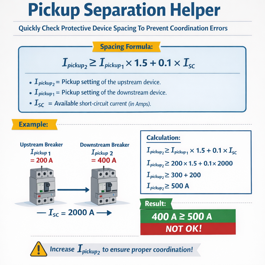
Pickup Separation Helper – Evaluate Protective Device Pickup Spacing to Avoid Miscoordination
Principles of Pickup Separation and Why It Matters
Pickup separation refers to the defined gap between the pickup thresholds of successive protective devices so that the correct device operates first during a fault. Proper spacing limits nuisance tripping, prevents unnecessary outages, and preserves selectivity across distribution and transmission systems.
Pickup Separation Helper is a practical verification approach that quickly checks current and time margins, CT ratios, and relay operating curves to prevent coordination errors during commissioning and routine audits.
Key objectives of pickup-separation verification
- Ensure downstream protective device operates for local faults before upstream devices.
- Provide margins to account for CT errors, relay tolerance, and transient phenomena like inrush.
- Minimize backup operations and reduce customer outage scope.
- Document settings to be compliant with utility coordination criteria and industry standards.
Essential Parameters for Rapid Pickup Separation Checks
Pickup Separation Helper focuses on a small set of values that enable fast decisions: relay pickup currents, CT ratios, time dial settings (TMS), curve types, and coordination margins.
Primary quantities and conversion formulas
Converting between primary current (I_primary) and relay secondary current (I_relay) uses CT ratio:
Variables:
- I_relay: secondary current delivered to relay (A), typical 0.1 A to 5 A depending on relay setting units.
- I_primary: actual conductor or bus current (A).
- CT_ratio: conventional primary:secondary ratio, e.g., 400:5, 800:5.
Time coordination basic rule:
Formula: T_upstream ≥ T_downstream + Coordination_margin
Variables:
- T_upstream, T_downstream: operating times at the fault current for upstream and downstream relays (s).
- Coordination_margin: safety margin (s), typical values 0.2–0.5 s for breakers, 0.1–0.3 s for solid-state relays depending on breaker trip times.
Inverse-time relay equation (generic form used for lookup and calculation):
Formula: T = A × TMS / ( (I / Is)B - 1 )
Variables:
- T: operating time (s).
- A, B: curve constants (dimensionless). Typical example values will be presented in the next table.
- TMS: time multiplier setting (dimensionless), typically 0.05 to 1.2 in practice.
- I: fault current seen by relay (A) (secondary).
- Is (or Ir): relay pickup current (secondary) (A).
Typical Values and Margins: Reference Tables
Below are common reference tables provided for engineers performing fast verification using Pickup Separation Helper. Use them for preliminary checks; always refer to relay vendor curves and system studies for final settings.
| System Level | Typical Downstream Pickup (Primary) | Typical Upstream Pickup (Primary) | Recommended Pickup Separation Factor | Recommended Time Coordination Margin |
|---|---|---|---|---|
| Low Voltage (LV) <1 kV | 50–500 A | 75–800 A | 1.2–1.7 × downstream pickup | 0.2–0.5 s |
| Medium Voltage (MV) 1–35 kV | 100–3000 A | 150–4500 A | 1.25–1.6 × downstream pickup | 0.3–0.8 s |
| High Voltage (HV) >35 kV | 500–10000 A | 750–15000 A | 1.3–2.0 × downstream pickup | 0.5–1.5 s |
| Relay Curve Type | Common Application | Typical A Constant | Typical B Constant | Notes |
|---|---|---|---|---|
| Standard Inverse | General distribution feeder protection | 0.14 | 0.02 | Often used for utility feeders; moderate inverse action |
| Very Inverse | Transformer backup and high X/R circuits | 13.5 | 1.0 | Much slower at low multiples; faster at high multiples |
| Extremely Inverse | Motor protection and heavy inrush environments | 80 | 2.0 | Strongly inverse; suitable for motor overload coordination |
| Definite Time | Backup protection where time is fixed | N/A | N/A | Operating time independent of current magnitude beyond pickup |
| Typical CT Ratios | Primary Range (A) | Secondary Nominal (A) | Common Applications |
|---|---|---|---|
| 100:5 | 0–100 A | 5 A | Small LV feeders and meters |
| 400:5 | 0–400 A | 5 A | Large LV feeders, distribution |
| 800:5 | 0–800 A | 5 A | MV feeders and transformers |
| 2000:5 | 0–2000 A | 5 A | Large MV/HV bus protection |
How Pickup Separation Helper Works — Step-by-Step Workflow
- Collect key data: downstream pickup (relay secondary), downstream CT ratio, upstream pickup, upstream CT ratio, relay curve types, and breaker trip times.
- Convert pickup settings to common basis (primary amps) using CT conversion formulas.
- Apply pickup separation factor: verify upstream_primary_pickup ≥ downstream_primary_pickup × separation_factor.
- Calculate operating times for fault levels at both relays using curve equations or vendor tables.
- Verify time coordination: T_upstream ≥ T_downstream + coordination_margin.
- Flag any violations and propose adjusted pickups or TMS changes with minimal impact on selectivity.
Quick checks and heuristics
- If CT ratio mismatch or rounding causes potential ambiguity, increase separation factor by 0.05–0.1.
- When using digital relays with programmable pickup in secondary amps, verify low-end resolution to account for increments.
- Account for CT saturation under high fault currents — use CT knee-point and saturation tests for final coordination.
- Include breaker operating times (mechanical delay, relay pickup-to-trip communication latency) in coordination margin.
Real Case Study 1 — Distribution Feeder Coordination
Scenario: A 480 V distribution bus has a downstream feeder protected by an electronic overcurrent relay (Relay D). An upstream feeder breaker (Relay U) provides backup protection for multiple feeders. Rapid verification using Pickup Separation Helper will check pickup separation and time coordination.
Given data
- Downstream Relay D: pickup set to 1.0 A (relay secondary units).
- Downstream CT ratio: 400:5.
- Upstream Relay U: pickup set to 1.5 A (secondary).
- Upstream CT ratio: 800:5.
- Relay curve type both: Standard Inverse with A=0.14, B=0.02 (use as approximate curve constants for calculation).
- Desired coordination margin: 0.3 s.
- Fault to evaluate: 4000 A primary bolted fault at feeder downstream location (primary). Convert to relay secondary currents.
Step 1 — Convert pickups to primary basis
Downstream primary pickup calculation:
Step 2 — Verify pickup separation factor
Result: 3.0 > typical requirement 1.2–1.7 → PASS for pickup separation.
Step 3 — Compute relay operating currents at fault
Convert fault current into relay secondary quantities:
Step 4 — Compute operating times using generic inverse formula
Formula: T = A × TMS / ( (I / Is)B - 1 )
We choose TMS = 0.2 for both relays initially. Is is relay pickup (secondary): Is_D = 1.0 A, Is_U = 1.5 A.
Downstream operating time (T_D):
T_D = 0.14 × 0.2 / ( (50)0.02 - 1 )
Compute (50)0.02 = e0.02 × ln(50) ≈ e0.02 × 3.9120 = e0.07824 ≈ 1.08138
Upstream operating time (T_U):
(16.6667)0.02 = e0.02 × ln(16.6667) ≈ e0.02 × 2.8109 = e0.05622 ≈ 1.0579
Step 5 — Verify time coordination
Check: T_U ?≥ T_D + coordination_margin
T_U = 0.483 s < 0.644 s → FAIL for time coordination at current TMS settings.
Solution and adjustment
- Increase upstream TMS to increase T_U. Solve for TMS such that T_U_new ≥ 0.644 s.
- From formula: TMS_required = T_target × ( (I/Is)B - 1 ) / A
Compute ((I/Is)B - 1) for upstream: (16.6667)0.02 - 1 ≈ 1.0579 - 1 = 0.0579
Set upstream TMS to 0.27 (rounded) → T_U_new ≈ 0.644 s → PASS.
Engineering notes
- Pickup separation is ample (factor 3), so adjusting TMS introduces no pickup overlap risk.
- Confirm CT accuracy and secondary wiring to ensure no unexpected saturation that compresses time margins.
- Document the change and update relay setting files; run a secondary injection test to confirm operation.
Real Case Study 2 — Transformer Backup and Inrush Considerations
Scenario: A 5 MVA step-down transformer protected primarily by a differential relay with restricted earth-fault (REF). An overcurrent relay at transformer LV provides backup. Pickup separation must prevent backup relay tripping during inrush, while ensuring backup operation for internal faults undetected by differential protection.
System data
- Transformer vector: 13.8 kV / 480 V, 5 MVA.
- Transformer rated LV current: I_rated = 5,000,000 VA / (√3 × 480 V) ≈ 6019 A (three-phase), per phase ≈ 6019 A/√3? For simplicity, use per-phase basis—practical setting uses line currents.
- Transformer LV backup relay (Relay T): overcurrent relay with pickup set to 1.2 × rated load. Relay secondary pickup Is_T = set accordingly per CT.
- Upstream feeder relay (Relay U) for the primary bus: upstream pickup higher. Coordination margin required to avoid backup operation during inrush (transient high currents during energization).
- CT ratios: LV CT for Transformer backup: 3000:5. Upstream CT: 4000:5.
- Inrush currents: peak inrush primary up to 10–12 × rated for a few cycles but nonlinear and decaying. Differential relay restraining measures prevent mis-operation, but backup overcurrent must be set to avoid tripping on inrush.
Step 1 — Determine rated and pickup currents
Transformer full-load primary current on LV (line) basis:
Convert to relay secondary pickup using LV CT 3000:5:
Step 2 — Upstream pickup and separation
Upstream CT 4000:5; if upstream relay pickup is set to primary 9000 A:
Convert to primary basis for separation check:
Separation factor = 9000 / 7223 ≈ 1.246 → Acceptable if minimum requirement 1.2–1.3; borderline.
Step 3 — Inrush consideration
Magnetizing inrush may produce primary currents up to 12 × rated for several cycles. If backup pickup primary is 7223 A, inrush peaks may exceed backup pickup and risk undesired tripping unless restrained.
Mitigation options:
- Increase backup pickup above typical inrush peak margin while maintaining backup effectiveness for internal faults.
- Implement time-delay or harmonic restraint in the backup relay to block tripping during first-cycle inrush (many digital relays offer 2nd-harmonic restraint).
- Rely on differential relay; ensure REF settings and CT ratios are correct and differential stability is proven under inrush tests.
Proposed solution and verification
Option chosen: add 2-second definite time delay to backup relay and enable 2nd-harmonic restraint (percentage). Verify that for an inrush of 12 × rated lasting <0.5 s, the backup relay will not trip: the harmonic restraint and time delay must prevent operation.
Compute operating time for a Phase-to-phase internal fault producing 20,000 A primary:
T = 0.14 × 0.4 / ( (2.77)0.02 - 1 )
(2.77)0.02 ≈ e0.02 × ln(2.77) ≈ e0.02 ×1.018 ≈ e0.02036 ≈ 1.02057
T ≈ 0.056 / (0.02057) ≈ 2.72 s
Because a definite 2 s delay was added, total time ≈ 2 + 2.72 = 4.72 s, which is acceptable as backup for severe internal faults. The system designer must evaluate whether that delay meets reliability constraints; alternative is to raise pickup to avoid inrush but that compromises sensitivity.
Engineering notes
- Use harmonic restraint: set second-harmonic percentage threshold to detect inrush and block backup relay during energized conditions.
- If raising pickup, re-evaluate sensitivity for internal transformer winding faults and ensure differential protection remains primary clearing method.
- Document setting rationale, and perform energization tests with controlled inrush simulation to validate behavior.
Common Coordination Errors and How Pickup Separation Helper Detects Them
- Undersized pickup spacing due to CT ratio rounding or misinterpretation: solved by converting to a common primary basis and checking separation factors.
- Time margin insufficiency because of varying curve constants: solved by computing actual operating times at expected fault currents and comparing with margins.
- CT saturation compressing apparent pickup separation at high fault currents: solved by including CT knee-point and saturation characteristics in the analysis and increasing separation factor or using IDMT curves with restraint.
- Relay damping, communication delays, or breaker trip coil variability ignored: solved by adding mechanical trip-time allowances to coordination margin.
Implementation Best Practices and Checklist
- Collect accurate equipment data: CT ratios, CT accuracy class, knee-point voltage, relay model and firmware, breaker trip times, and system short-circuit levels.
- Perform pickup conversion to common unit (primary amps) for all devices in the coordination chain.
- Apply a minimum separation factor; use utility-specific criteria (commonly 1.2–1.6) and increase it near CT ratio discontinuities.
- Calculate operating times with vendor-supplied curves or using standardized equations; verify T_upstream ≥ T_downstream + margin.
- Include dynamic phenomena (inrush, DC offset) and CT saturation tests in the final verification plan.
- Document every change and store setting files in a version-controlled repository; perform secondary injection testing to validate expected behavior.
Regulatory and Standards References
Pickup Separation Helper aligns with established standards and industry best practices. Key references include:
- IEEE Std C37.112 — Standard Inverse Time Characteristics for Overcurrent Relays. See: https://standards.ieee.org/
- IEEE Std C37.2 — Electrical Power System Device Function Numbers. See: https://standards.ieee.org/
- IEC 60255 — Electrical relays. Time-current characteristics and relay testing. See: https://www.iec.ch/
- NERC PRC standards and regional coordination guides for bulk power system protection. See: https://www.nerc.com/
- NFPA 70 (National Electrical Code) for equipment protection and system practices. See: https://www.nfpa.org/
For full compliance and vendor-specific implementation consult relay manuals and utility coordination manuals.
Automation and Tools Integration
Pickup Separation Helper is often implemented inside protection coordination tools and relay setting software; automated scripts compute conversions, evaluate curve intersections, and output recommended TMS or pickup adjustments.
Essential outputs for an automated helper
- List of devices with primary-equivalent pickup values and separation factors.
- Operating time tables at a set of fault current levels (e.g., 2×, 5×, 10× pickup).
- Flags for potential miscoordination: pickup violation, time violation, CT saturation risk, or inrush vulnerability.
- Suggested corrective actions: increase upstream TMS, adjust pickup, enable harmonic restraint, or change CT ratio.
Summary of Practical Recommendations
- Always normalize pickup values to primary quantities before comparing devices.
- Apply sensible separation factors (1.2–1.6) and conservative margins where CTs differ or where saturation is likely.
- Combine pickup separation checks with operating time calculations using actual curve equations or vendor tables.
- Consider dynamic phenomena: inrush, DC offset, CT saturation, and breaker mechanical delays when finalizing settings.
- Validate settings with secondary injection and on-site commissioning tests.
Further Reading and Authoritative Links
- IEEE Standards Association — https://standards.ieee.org/ (search for C37.112 and C37.2 for inverse-time and device function guides).
- IEC Central Office — https://www.iec.ch/ (see IEC 60255 series for relay testing and characteristics).
- NERC Reliability Standards — https://www.nerc.com/ (for bulk electric system protection coordination requirements).
- NFPA Codes and Standards — https://www.nfpa.org/ (relevant codes for electrical installations and protection practices).
Final engineering note
Pickup Separation Helper provides a rapid, defensible method to detect coordination errors and propose minimal corrective actions. It is a first-line verification tool; always corroborate its recommendations with full system studies and hardware testing to ensure protection dependability and security.