Electrical calculations demand precision, safety, and efficiency for compliant residential installations every professional must ensure.
A robust home electrical calculator reduces errors, saves time, and enforces regulatory design constraints effectively.
Home Electrical Calculator — Circuit Current, Breaker, Conductor & Voltage Drop
Essential capabilities of a home electrical calculator
- Load modeling: supports individual appliances, diversified loads, and continuous vs non-continuous classification.
- Conductor ampacity selection: uses material, insulation temperature rating, installation method, and correction factors.
- Voltage drop analysis: single-phase and three-phase calculations including conductor resistance and reactance.
- Protective device coordination: fuse and breaker selection, trip curves, and selective coordination checks.
- Short-circuit and prospective fault current estimation: calculates available fault currents for device interrupting ratings.
- Earthing/grounding checks: earth electrode resistance, earth-fault loop impedance, and RCD/MPPE coordination.
- Standards compliance: integrates regional normative parameters (NEC, IEC, local amendments).
- Report generation: clear calculation reports, assumptions, and reference citations for permitting or inspection.
Core calculations and formulas for residential electrical design
Ohm’s Law and basic power relationships
Fundamental formulas used everywhere in residential work:
Where:
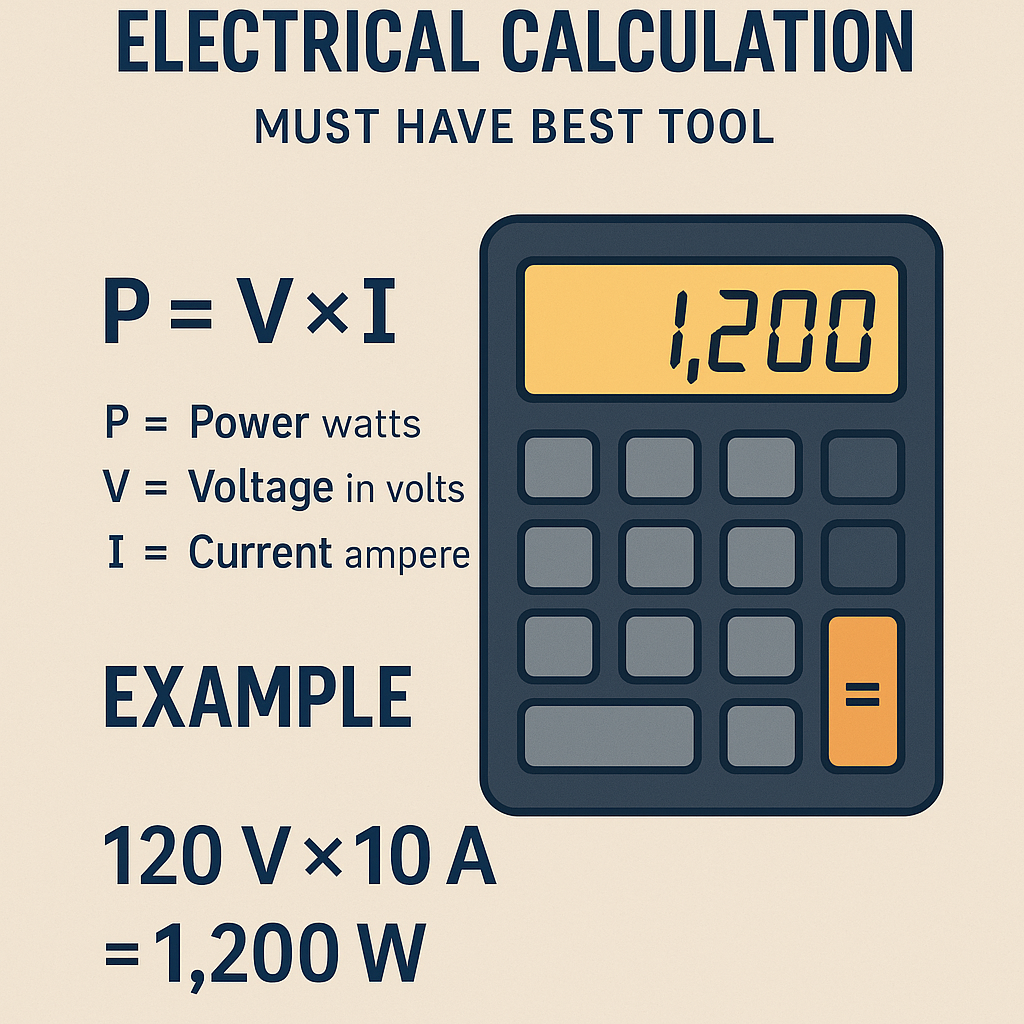
- V = voltage (volts, V). Typical residential values: 120 V (single-phase branch), 240 V (single-phase supply), 208 V or 400 V (three-phase in some regions).
- I = current (amperes, A). Typical branch-circuit currents: 15 A, 20 A, 30 A, etc.
- R = resistance (ohms, Ω). Typical conductor resistances depend on size and material (see tables below).
- P = active power (watts, W) or kilowatts (kW). Typical appliance powers: range from 40 W (lighting) to 3000 W (electric range element).
Load estimation and demand factors
Accurate load estimation is the first step. Summation of individual appliance ratings produces the connected load. Apply demand factors and diversity rules per applicable standard.
Typical working formula for connected load and design current:
But most codes require application of demand factors:
Where DF = demand factor (unitless), typically less than 1. Example typical values: general lighting DF = 1.0 for small homes but 0.4–0.8 for diversified household loads depending on code.
| Appliance / Circuit | Typical Power (W) | Typical Demand Factor | Notes |
|---|---|---|---|
| LED lighting (per circuit) | 200–800 | 1.0 | Depends on number of fixtures |
| General receptacles (per room) | 600–1500 | 0.8 | Includes small appliances |
| Electric range (dual element) | 8000–12000 | 0.65–1.0 | Often treated as separate large appliance |
| Clothes dryer (electric) | 4000–6000 | 1.0 | Continuous if frequent use |
| Oven | 3000–5000 | 1.0 | Large fixed appliance |
| Dishwasher | 1200–1800 | 1.0 | Intermittent operation |
| Garbage disposal | 500–1000 | 0.6 | Short duration |
| Electric water heater | 3000–4500 | 0.8 | Consider simultaneous usage |
| Air conditioning (split) | 2000–5000 | 1.0 | Motor loads, starting currents must be considered |
Conductor ampacity and adjustment factors
Basic sizing process: determine required current, select conductor with ampacity >= required current adjusted for continuous load multipliers and correction factors.
Common rule for continuous loads: apply 125% multiplier to continuous currents.
Then select conductor size with ampacity >= A_req considering temperature correction and grouping factors.
| Conductor Size (mm2 / AWG) | Copper Ampacity @ 60°C (A) | Copper Ampacity @ 75°C (A) | Typical Use |
|---|---|---|---|
| 1.5 mm2 (AWG 16) | 18 | 20 | Lighting circuits in many regions |
| 2.5 mm2 (AWG 14) | 24 | 30 | Small power circuits, general receptacles |
| 4 mm2 (AWG 12) | 32 | 40 | Small motors, longer runs |
| 6 mm2 (AWG 10) | 41 | 55 | Cooktop legs, moderate loads |
| 10 mm2 (AWG 8) | 65 | 70 | Small feeders, subpanels |
| 16 mm2 (AWG 6) | 90 | 100 | Main feeders for small homes |
| 25 mm2 (AWG 3) | 120 | 130 | Large feeders and service conductors |
| 35 mm2 | 150 | 170 | High-demand feeders |
Voltage drop calculation and acceptable limits
Voltage drop must be checked for long runs. Typical recommended maximum voltage drop at farthest outlet: 3% for branch circuits and 5% total supply including feeder.
Single-phase formula (linear conductor, copper):
Three-phase formula (line-to-line):
Where:
- V_drop = voltage drop (V)
- I = circuit current (A)
- R = conductor resistance per unit length (Ω/m)
- Z = magnitude of conductor impedance per unit length (Ω/m)
- L = one-way length of conductor (m)
Example typical resistances for copper (at 20°C):
| Conductor (mm2) | Resistance (Ohm/km) | Resistance (Ohm/m) | Notes |
|---|---|---|---|
| 1.5 | 12.1 | 0.0121 | Small lighting conductors |
| 2.5 | 7.41 | 0.00741 | General power and lighting |
| 4 | 4.61 | 0.00461 | Longer branch runs |
| 6 | 3.08 | 0.00308 | Cooktops, small motors |
| 10 | 1.83 | 0.00183 | Feeders and subpanels |
| 16 | 1.15 | 0.00115 | Service mains for small houses |
| 25 | 0.727 | 0.000727 | Large feeders |
Short-circuit current estimation
Prospective short-circuit current (PSC) at a point can be estimated from source voltage and the Thevenin equivalent impedance:
Where:
- I_sc = short-circuit current (A)
- V_nom = nominal system voltage (V)
- Z_th = total source-to-point impedance (Ω)
Accurate PSC requires utility transformer impedance, conductor impedances, and motor contributions. Use conservative assumptions or utility data if available.
Functional UX and data inputs every calculator must support
- Unit selection: automatic conversion between AWG and mm2, volts (V), kilovolts (kV), ohms, meters, feet.
- Regional code presets: NEC (USA), IEC 60364 (international), BS7671 (UK), AS/NZS (Australia/New Zealand).
- Temperature correction factors and ambient temperature inputs.
- Grouping and conduit fill correction factors.
- Harmonic content input for non-linear loads affecting neutral sizing.
- Report export: PDF with step-by-step calculations, inputs, assumptions, and normative references.
Practical examples with complete solutions
Example 1 — Kitchen branch circuit design including voltage drop
Scenario: Design a dedicated circuit for an electric range element rated 8000 W, located 12 meters from the distribution board, single-phase 240 V supply. Copper conductors are used. Maximum allowable voltage drop for the branch: 3%.
Step 1 — Determine operating current:
Step 2 — Continuous load check:
If the appliance is considered continuous (operates more than 3 hours), apply 125% multiplier. Many standards treat fixed cooking appliances as non-continuous; assume conservative continuous designation for this example:
Step 3 — Select breaker and conductor ampacity:
Choose next standard breaker rating >= I_design. Standard breaker sizes: 40 A, 50 A. 41.67 A exceeds 40 A, so choose 50 A breaker.
Conductor ampacity must be >= breaker rating (and >= 125% continuous current where applicable). For 50 A, typical copper conductor choices:
- 6 mm2 copper @ 75°C has ampacity ~55 A — acceptable
- 10 mm2 copper @ 75°C has ampacity ~70 A — also acceptable
Select 6 mm2 as minimum acceptable based on ampacity. Verify derating factors if more than three conductors in same conduit, ambient temperature adjustments, or insulation rating differences.
Step 4 — Voltage drop check using single-phase formula:
Use actual operating current for voltage drop (not 125% unless required by code for voltage drop). Use I = 33.33 A.
From table, R for 6 mm2 ≈ 0.00308 Ω/m.
V_drop = 2 * 33.33 A * 0.00308 Ω/m * 12 m = 2 * 33.33 * 0.00308 * 12
Result: Voltage drop 1.03% < 3% acceptable. Final selection: 50 A breaker with 6 mm2 copper conductor, confirm terminations and derating.
Example 2 — Long feeder to subpanel, three-phase supply with voltage drop and conductor sizing
Scenario: A three-phase 400 V (line-to-line) feeder supplies a subpanel 150 meters away. Connected loads at subpanel: small motor + lighting + receptacles totaling 12 kW balanced across phases. Motor starting currents require additional consideration. Use copper conductors and limit feeder voltage drop to 3% of 400 V (i.e., 12 V).
Step 1 — Determine phase current from balanced three-phase load:
Step 2 — Continuous load consideration:
If some loads are continuous, apply 125% where required. Assume the whole load is not continuous; use 17.32 A as operating current for voltage drop. For conductor sizing per ampacity select a conductor with ampacity >= expected maximum current plus motor starting considerations; choose to allow 2× running current for starting surge transient if motor coupling is direct-on-line, but protective device selection will handle inrush.
Step 3 — Voltage drop calculation for three-phase feeder (approximate using resistance only):
Select a conductor trial: 10 mm2 copper, R ≈ 0.00183 Ω/m.
Percent drop = (8.235 / 400) * 100 = 2.06% which is below 3% target — acceptable.
Step 4 — Ampacity check:
10 mm2 copper @ 75°C ampacity ~70 A, far above 17.32 A, so ampacity is acceptable. If future load growth is expected, specify larger conductor or spare capacity.
Step 5 — Short-circuit and protection verification:
Estimate PSC at feeder incoming point based on transformer impedance or utility data. Select protective device upstream with interrupt capacity exceeding prospective short-circuit. Ensure selectivity if multiple devices are in series.
Result: 10 mm2 copper conductor satisfies voltage drop and ampacity for current load. Provide notes: verify motor starting current (inrush) to ensure thermal and magnetic protection settings, and review harmonics for neutral sizing.
Advanced topics calculators should cover
Neutral conductor sizing with harmonic loads
Non-linear loads create triplen harmonics that sum in neutral. For buildings with multiple electronic devices, calculate neutral current using harmonic spectrum or apply derating factors. In extreme cases, oversize neutral or use multiple neutrals.
Ground-fault loop impedance and RCD coordination
Earth-fault loop impedance must be low enough to allow protective devices to operate within disconnection times. A calculator should compute loop impedance Z_s and check against required maximum Z_max for a given protective device and supply voltage.
Basic check: Z_s <= U_o / I_trip_required
Where U_o = nominal voltage to earth; I_trip_required = device trip current at required disconnection time.
Harmonic distortion and derating
High harmonic content increases conductor heating. Calculators should support THD inputs and apply multiplicative derating to ampacity or recommend mitigation (filters, oversized neutrals).
Regulatory references and authoritative resources
Designers must reference regional and international standards. Important documents and sources include:
- National Electrical Code (NEC), NFPA 70 — official site: https://www.nfpa.org/ — consult latest edition for USA rules.
- IEC 60364 — International standard for electrical installations: https://www.iec.ch/
- BS 7671 (IET Wiring Regulations) — UK standard: https://www.theiet.org/
- IEEE standards for grounding and short-circuit analyses (IEEE Std 80, others): https://standards.ieee.org/
- Manufacturer datasheets and utility fault current data — critical for accurate PSC and protective device selection.
Best practices for validation and reporting
- Record every assumption: ambient temperature, conductor insulation rating, conduit fill, grouping, and diversity factors.
- Provide a clear calculation chain for inspectors and contractors: show raw inputs, intermediate steps, and final selections.
- Include contingencies: specify next larger conductor size where voltage drop is marginal or future expansion is likely.
- Use conservative rounding rules and state rounding policy in reports.
- Cross-check with manufacturer motor curves and protective device time-current characteristics when motors are present.
Implementation checklist for the ideal calculator tool
- Support for multiple standards and automatic selection of code-based demand/diversity factors.
- Interactive input forms with per-circuit detail, grouping options, and drag-and-drop load placement for UX.
- Automated tables: conductor ampacity, resistance, reactance, and standard protective devices.
- Exportable, auditable calculation reports with hyperlinked normative references and versioning.
- Scenario comparison mode: quickly compare two sizing strategies or conductor types (copper vs aluminum).
- Customizable safety margins and user-defined local amendments or utility transformer data.
Common pitfalls and how calculators avoid them
- Ignoring ambient temperature and conduit correction factors — incorporate automatic temperature derating.
- Using operating current for conductor sizing when continuous load rules require 125% — flag continuous items automatically.
- Neglecting voltage drop for long runs — include run-length warnings and automatic re-sizing suggestions.
- Assuming balanced three-phase when loads are unbalanced — allow phase-by-phase entries and show neutral currents.
- Forgetting harmonics — offer harmonic input and neutral ampacity assessment.
Maintenance, updates, and legal use notes
- Regularly update the calculator database with the latest code editions and manufacturer catalogs.
- Keep a changelog of normative parameter updates and publish it with each calculation report.
- Clarify that calculator outputs are design aids; final responsibility rests with a licensed electrical engineer or authority having jurisdiction.
Additional extensive tables of common design parameters
| Standard Breaker Size | Typical Use | Minimum Copper Conductor (mm2) | Notes |
|---|---|---|---|
| 15 A | Lighting circuits (120 V) | 1.5 mm2 | Check local minimum conductor rules |
| 20 A | General outlets (120 V) | 2.5 mm2 | Often used for receptacles |
| 30 A | Small appliances | 4 mm2 | Kitchen receptacles in some regions |
| 40 A | Cooktop legs, medium loads | 6 mm2 | May be used for ranges with combined legs |
| 50 A | Electric range or large fixed appliance | 6–10 mm2 | Confirm with local code and equipment datasheet |
| 100 A | Main service for small homes | 25 mm2 | Service conductors often larger; consult service equipment |
| Conductor | Resistivity at 20°C (Ω·mm2/m) | Correction factor @ 30°C | Typical reactance (mΩ/m) |
|---|---|---|---|
| Copper 1.5 mm2 | 0.0182 | 0.95 | 0.08 |
| Copper 2.5 mm2 | 0.0182 | 0.96 | 0.07 |
| Copper 6 mm2 | 0.0182 | 0.98 | 0.06 |
| Copper 10 mm2 | 0.0182 | 0.99 | 0.055 |
| Aluminum 16 mm2 | 0.0282 | 0.90 | 0.09 |
References and further reading
- NFPA 70, National Electrical Code (NEC). Available at: https://www.nfpa.org/
- IEC 60364 — Electrical installations of buildings. Details available through IEC: https://www.iec.ch/standards
- IET Wiring Regulations (BS 7671). Information: https://www.theiet.org/
- IEEE Std 80 — Guide for safety in AC substation grounding. https://standards.ieee.org/
- Manufacturer datasheets for cable resistance and ampacity (e.g., Prysmian, Nexans) — consult vendor pages for precise tables.
- Utility coordination documents and short-circuit data — contact local utility for transformer impedance and available fault current data.
Final operational recommendations
- Always validate calculator outputs with site verification and manufacturer data.
- Document every assumption in exported reports to maintain traceability for code compliance and inspections.
- When in doubt on protective device coordination or fault calculations, consult a licensed electrical engineer and supply-side utility data.
Well-configured calculators are essential tools for modern residential electrical design, improving safety, compliance, and efficiency.