This article presents an advanced transformer losses calculator tailored for IEC and IEEE compliance applications.
It combines core, copper, dielectric losses, stray components, and load curves into precise estimations rapidly.
Transformer Losses Calculator — IEC / IEEE Practical Tool
Overview of loss mechanisms in power transformers
Accurate transformer loss estimation requires separating no-load and load-dependent components. No-load (core/excitation) losses depend on magnetic flux and frequency; load losses include copper winding losses, stray/structural losses, and dielectric/insulation losses. A robust calculator must implement physics-based formulas, temperature dependence, material parameters, and standards-based correction factors (IEC, IEEE) to provide reliable results for design, procurement, or lifecycle cost analysis.Key objectives of an IEC/IEEE-aligned calculator:- Generate P0 (no-load/core) and Pload components with traceable formulae.
- Allow temperature and loading profiles to compute energy losses over time (kWh/year).
- Provide normative compliance checks and reportable output for specification and tender documentation.
Mathematical model and core equations
A clear separation of terms is required. The total transformer losses at operating conditions are:Ptotal = Pcore + PCu + Pstray + Pdielectric + Pexcitation
Where:- Pcore: core (iron) losses at rated flux and frequency
- PCu: copper (I2R) losses in windings at operating temperature
- Pstray: stray (structural, eddy in tank/structural parts) losses
- Pdielectric: dielectric dissipation losses in insulation and bushings
- Pexcitation: additional magnetizing losses if applicable (often included in Pcore)
Core loss modeling (Steinmetz-type)
A general empirical core loss expression used in calculators:Pcore = kc × fa × Bb × Vcore
- kc: material constant (W/(m3 × Hza × Tb)). Typical range: 1–12 for grain-oriented steels depending on grade.
- f: frequency in Hz. Typical values: 50 or 60.
- a: frequency exponent. Typical values: 0.9–1.5 depending on the Steinmetz model variant.
- B: peak flux density in Tesla. Typical design values: 1.6–1.95 T for distribution transformer cores.
- Vcore: core volume in m3.
Pcore(rated) is often provided directly by the manufacturer and corrected for voltage and frequency by simple proportional scaling:
Pcore(U, f) = Pcore,rated × (U / Urated)m × (f / frated)n
Where m ≈ 2–3, n ≈ 0.9–1.5 depending on core material and magnetizing characteristics.Copper loss (I²R) with temperature correction
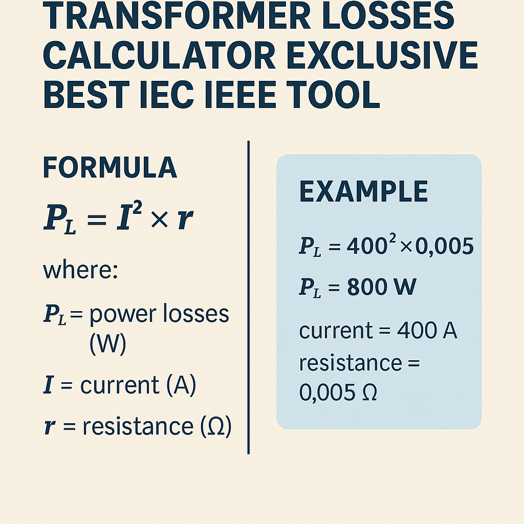
Fundamental formula:PCu = I2 × R(T)
Resistance temperature dependence:R(T) = R20 × [1 + α × (T - 20)]
Variables and typical values:- I: RMS current through winding at operating load (A).
- R20: DC resistance at 20 °C (Ω). Example for copper: use standard tables below.
- α: temperature coefficient for copper ≈ 0.00393 per °C.
- T: winding operating temperature in °C (hot-spot or measured conductor temperature).
Extensive material and typical parameter tables
| Conductor | Cross-sectional area (mm²) | DC resistance at 20 °C (Ω/km) | Typical ampacity (A) |
|---|---|---|---|
| Copper AWG 1/0 | 53.5 | 0.377 | 150–200 |
| Copper 95 mm² | 95 | 0.193 | 200–260 |
| Copper 150 mm² | 150 | 0.122 | 260–350 |
| Copper 240 mm² | 240 | 0.077 | 350–430 |
| Copper 400 mm² | 400 | 0.046 | 500–650 |
| Core steel grade | Typical Bmax (T) | Typical core loss density (W/kg at 50 Hz) |
|---|---|---|
| Grain-oriented CRGO | 1.6–1.9 | 0.4–1.0 |
| Non-oriented electrical steel | 1.3–1.6 | 1.0–3.0 |
| Amorphous metal | 1.0–1.3 | 0.2–0.6 |
| Loss component | Typical percentage distribution (distribution transformer) | Notes |
|---|---|---|
| Core (no-load) | 30–60% | Dominates at light load; independent of load current |
| Copper (load) | 30–60% | Proportional to I², increases with load |
| Stray/structural | 5–15% | Design dependent; increases with load |
| Dielectric | 1–5% | Low but important for high-voltage insulation |
Dielectric and stray loss estimation methods
Dielectric loss in insulation can be estimated from measured tan δ or dissipation factor:Pdielectric = V2 × ω × C × tanδ
Where:- V: RMS line-to-ground voltage across the dielectric (V)
- ω = 2πf
- C: capacitance (F)
- tanδ: dissipation factor of insulation (dimensionless). Typical values vary: oil-paper systems 0.01–0.05, solid polymer insulation lower.
Pstray = ks × I2
Where ks (Ω equivalent) is empirically derived from measurement or design database. Typical ks values depend on transformer size; for a distribution transformer they might be in the range 0.002–0.01 Ω equivalent for the winding arrangement.Frequency and voltage correction for manufacturer data
When manufacturer provides Pcore,rated and Pload,rated at rated voltage/frequency, scale for operating voltage and frequency:Pcore(U,f) = Pcore,rated × (U / Urated)m × (f / frated)n
Common exponents: m ≈ 2.0–3.0 (voltage dependence), n ≈ 0.9–1.5 (frequency). Use manufacturer guidance or measured test data for precise exponents.Energy calculation and annual losses
To convert instantaneous losses to annual energy losses use load profile integration:Eyear = ∑ ( Ptotal(t) × Δt ) over 8760 hours
For discrete typical load points:Eyear = ∑i Ptotal(Li) × hours(Li)
Where Li is load fraction (0–1), and Ptotal(L) accounts for I = L × Irated and temperature-dependent R(T).Calculator workflow and algorithmic steps
An effective tool follows these steps:- Input transformer nameplate: rated power Srated, rated voltage, rated current, impedance %, R20, manufacturer test losses (Pcore,rated, PCu,rated), core material and volume, conductor sizes.
- Define operating conditions: system voltage, frequency, ambient temp, oil/winding hottest-spot rise, and load profile (hourly or block).
- Compute temperature-corrected R and copper losses per load point.
- Compute core losses using Steinmetz or manufacturer scaling.
- Estimate stray and dielectric losses using empirical coefficients or measured data.
- Integrate energy over time to yield annual kWh losses and operating cost using energy price.
- Provide sensitivity analysis: impact of ambient temperature, life-cycle cost, and loss-replacement trade-offs.
Worked Example 1: 100 kVA distribution transformer (50 Hz)
Problem statement: Calculate losses at rated conditions and annual energy losses for a 100 kVA, 400/230 V (LV 230 V line-to-neutral), 50 Hz distribution transformer. Manufacturer provides: Pcore,rated = 350 W (at rated voltage), measured PCu,rated = 1200 W (at rated current), R20 for LV winding = 0.015 Ω, rated LV current Irated = 100 kVA / (√3 × 230 V) ≈ 251.5 A. Assume ambient 25 °C, hot-spot rise leads to winding temperature T = 80 °C. Load profile: 50% load for 6000 hours, 100% load for 2000 hours, 0% for 760 hours.Step-by-step solution:- Compute temperature-corrected resistance:
R(T) = R20 × [1 + α × (T - 20)]
Using α = 0.00393 /°C, R20 = 0.015 Ω:R(80) = 0.015 × [1 + 0.00393 × (80 - 20)] = 0.015 × [1 + 0.00393 × 60]0.00393 × 60 = 0.2358 → R(80) = 0.015 × 1.2358 = 0.018537 Ω.
- Copper losses at rated current (100%):
PCu,100 = Irated2 × R(80)
Irated ≈ 251.5 A → I2 ≈ 63,253 A2.
PCu,100 = 63,253 × 0.018537 ≈ 1,173 W (close to manufacturer 1,200 W).
Use manufacturer PCu,rated=1,200 W if preferred to preserve test alignment. - At 50% load (L = 0.5), I = 0.5 × Irated:
PCu,50 = (0.5 Irated)2 × R(80) = 0.25 × PCu,100 ≈ 293 W.
- Core loss assumed independent of load (using manufacturer): Pcore = 350 W for rated conditions.
- Assume stray losses estimated at 8% of total load losses at rated load: Pstray,100 ≈ 0.08 × PCu,100 = 0.08 × 1,200 ≈ 96 W. At fractional load scale as I2, so at 50%: Pstray,50 ≈ 0.25 × 96 ≈ 24 W.
- Dielectric losses assumed small: 25 W constant.
- Compute total losses at each block:
At 100%: Ptotal,100 = 350 + 1,200 + 96 + 25 = 1,671 W.
At 50%: Ptotal,50 = 350 + 293 + 24 + 25 = 692 W.
At 0%: Ptotal,0 = 350 + 0 + 0 + 25 = 375 W.
- Annual energy:E = 1,671 W × 2,000 h + 692 W × 6,000 h + 375 W × 760 h
E = (3,342,000 + 4,152,000 + 285,000) Wh = 7,779,000 Wh = 7,779 kWh/year.
- Operating cost example: energy price $0.10/kWh → Annual loss cost = $777.9.
Worked Example 2: 10 MVA power transformer (60 Hz) with partial loading
Problem statement: Evaluate losses and energy consumption for a 10 MVA, 230/13.8 kV, 60 Hz power transformer. Manufacturer test data at rated conditions: Pcore,rated = 9,500 W, PCu,rated = 72,000 W. Rated HV current Irated = 10,000 kVA / (√3 × 230 kV) ≈ 25.13 A. Use operating average loading of 60% for 8,000 hours, 30% for 4,000 hours, and 10% for 760 hours. Ambient conditions cause winding temperature T = 95 °C. LV winding R20 not provided; use manufacturer PCu,rated directly for scaling.Solution:- Use manufacturer test losses and scale copper losses by load squared and apply temperature correction implicitly by test alignment.
PCu(L) = PCu,rated × L2
Examples:PCu,60 = 72,000 × 0.62 = 72,000 × 0.36 = 25,920 W.
PCu,30 = 72,000 × 0.09 = 6,480 W.
PCu,10 = 72,000 × 0.01 = 720 W.
- Core losses assumed constant at 9,500 W (unless voltage deviation requires scaling).
- Estimate stray losses as 7% of copper losses at rated:
Pstray,100 = 0.07 × 72,000 = 5,040 W.
Scale with L2.Pstray,60 = 5,040 × 0.36 = 1,814 W.
Pstray,30 = 5,040 × 0.09 = 453.6 W.
Pstray,10 = 5,040 × 0.01 = 50.4 W.
- Dielectric losses assumed 1,200 W constant.
- Total losses per block:
Ptotal,60 = 9,500 + 25,920 + 1,814 + 1,200 = 38,434 W.
Ptotal,30 = 9,500 + 6,480 + 453.6 + 1,200 = 17,634 W.
Ptotal,10 = 9,500 + 720 + 50.4 + 1,200 = 11,470.4 W.
- Annual energy:E = 38,434 W × 8,000 h + 17,634 W × 4,000 h + 11,470.4 W × 760 h
E = 307,472,000 + 70,536,000 + 8,717,504 Wh = 386,725,504 Wh ≈ 386,726 kWh/year.
- At $0.07/kWh energy price → Annual cost ≈ $27,071.
Standards, test methods and normative references
For regulatory and compliance alignment the calculator must reference authoritative standards and test methods:- IEC 60076 series — Power transformers. Key parts:
- IEC 60076-1: General — ratings and losses, tests.
- IEC 60076-2: Temperature rise.
- IEC 60076-7: Loading guide for transformers.
- IEEE Std C57.12.00 — Standard for general requirements for liquid-immersed distribution, power transformers.
- IEEE Std C57.91 — Guide for loading mineral-oil-immersed transformers.
- IEC/TR 60076-16 — Measurement of instrument transformer losses (where applicable).
- IEC standards pages: https://www.iec.ch/ (search IEC 60076)
- IEEE Standards Association: https://standards.ieee.org/ (search C57)
- NIST material properties resources: https://www.nist.gov/
- IEC product pages and summaries (example): https://webstore.iec.ch/ (for purchasing standards)
Uncertainty, calibration, and validation
A professional calculator must:- Allow input of measurement uncertainty for test-derived loss values and propagate to energy calculations.
- Compare laboratory short-circuit and open-circuit test results to modeled values and compute residuals for calibration.
- Include flagging when extrapolation outside manufacturer-specified voltage/frequency ranges is attempted.
- Winding temperature: demonstrate how ±10 °C affects PCu and annual energy.
- Load factor changes: show break-even of higher-efficiency core vs purchase premium.
- Material substitution (CRGO vs amorphous): quantify core loss reduction and payback time.
UX and reporting requirements for an IEC/IEEE-focused tool
Best-practice UX elements:- Form-based input with units and validation for all electrical, thermal, and geometric parameters.
- Pre-filled common transformer templates (distribution, power, instrument) and manufacturer libraries.
- Exportable compliance report showing:
- Test-based measured vs modeled losses and test references (IEC/IEEE clauses).
- Annual energy, CO2 equivalent (using user-provided grid emission factor), and cost.
- Sensitivity and what-if scenarios (percent load, ambient temperature).
- Graphical load-loss curves and a downloadable CSV of hourly loss time series.
Implementation tips and numerical stability
Practical considerations for developers and analysts:- Prefer manufacturer test values where available and use models for interpolation and scaling.
- Treat stray loss coefficients as empirical inputs with default recommendations per transformer class.
- Use double-precision arithmetic for power/energy accumulation to avoid rounding error across 8760 points.
- Allow both deterministic and probabilistic (Monte Carlo) modes to quantify uncertainty in annual energy.
Common pitfalls and mitigation strategies
- Incorrect temperature assumption for R(T): always clarify whether R20 refers to DC length or measured short-circuit winding resistance.
- Using linear scaling for core loss with voltage — core loss is nonlinear and should be scaled with appropriate exponent m (≥2) or Steinmetz model.
- Neglecting dielectric losses for high-voltage bushings and capacitive couplings — include when voltages exceed distribution levels.
- Omitting stray losses — these can represent 5–15% of total loss and impact energy estimates materially.
Validation checklist for IEC/IEEE compliance
Before issuing a compliance report, confirm:- Manufacturer test references (open-circuit and short-circuit) are included with dates and ambient conditions.
- Temperature correction method is documented and consistent with IEC 60076 temperature-rise methodology.
- Load profile source is documented (SCADA, metering, or engineering estimate).
- All assumptions and empirical coefficients are recorded and traceable.
References and further reading
- IEC 60076 series — Power transformers: https://www.iec.ch/
- IEEE Std C57.12.00 — General Requirements for Liquid-Immersed Distribution, Power, and Regulating Transformers: https://standards.ieee.org/
- IEEE Std C57.91 — Guide for Loading Mineral-Oil-Immersed Transformers: https://standards.ieee.org/
- Textbook reference: J. S. Rao, "Transformer Engineering: Design, Technology, and Diagnostics" (for deeper theoretical models).
- NIST material properties database (electrical steels): https://www.nist.gov/
Practical summary and recommended defaults
For a production-ready calculator, include the following default parameter set for common use-cases:- α (copper) = 0.00393 /°C.
- Stray loss coefficient default ranges:
- Small distribution: ks ≈ 0.003–0.01 Ω-equivalent scaling
- Large power: ks ≈ 0.001–0.005
- Core scaling exponents m = 2.2 for voltage, n = 1.0 for frequency as a starting baseline.
- Provide templates for amorphous cores vs CRGO to permit rapid payback analysis.