The conversion between volts (V) and volt-amperes (VA) is essential for electrical engineering applications. A Volts to VA calculator helps engineers accurately determine apparent power, including formulas, tables, and examples.
Volts ↔ VA Calculator (Bidirectional)
What is VA?
Power factor (PF)?
Understanding the Relationship Between Volts and VA
- Volts (V): The potential difference that drives electric current through a conductor.
- Volt-Amperes (VA): The unit of apparent power, representing the product of RMS voltage and RMS current in an AC system.
- Importance: While watts (W) measure real power, volt-amperes (VA) measure the apparent power required to supply a load, considering both active and reactive components.
In AC systems, equipment such as transformers, UPS systems, and power supplies are rated in VA, making it crucial to convert from volts to VA for proper design and compatibility.
Core Formula for Volts to VA Conversion
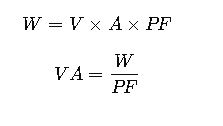
The general formula is:
Where:
- VA= Apparent Power (volt-amperes)
- V= Voltage in volts (RMS value in AC systems)
- A= Current in amperes
Extended Formulas Considering Power Factor
In AC circuits:
Where:
- W= Real power in watts
- PF = Power Factor (dimensionless, between 0 and 1)
Thus, the relationship between volts and VA depends not only on current but also on the power factor, which varies depending on the type of load (resistive, inductive, capacitive).
Common Values of Volts and Their Conversion to VA
Below is an extended table of commonly used voltage levels with different current ratings to show the corresponding apparent power (VA).
Table 1: Volts to VA Conversion (Single-Phase Systems)
| Voltage (V) | Current (A) | Apparent Power (VA) |
|---|---|---|
| 110 V | 1 A | 110 VA |
| 110 V | 5 A | 550 VA |
| 110 V | 10 A | 1100 VA |
| 120 V | 1 A | 120 VA |
| 120 V | 5 A | 600 VA |
| 120 V | 10 A | 1200 VA |
| 220 V | 1 A | 220 VA |
| 220 V | 5 A | 1100 VA |
| 220 V | 10 A | 2200 VA |
| 230 V | 1 A | 230 VA |
| 230 V | 5 A | 1150 VA |
| 230 V | 10 A | 2300 VA |
| 240 V | 1 A | 240 VA |
| 240 V | 5 A | 1200 VA |
| 240 V | 10 A | 2400 VA |
Table 2: Higher Voltage Levels (Industrial Applications)
| Voltage (V) | Current (A) | Apparent Power (VA) |
|---|---|---|
| 400 V | 5 A | 2000 VA |
| 400 V | 10 A | 4000 VA |
| 400 V | 50 A | 20,000 VA |
| 415 V | 10 A | 4150 VA |
| 415 V | 50 A | 20,750 VA |
| 480 V | 10 A | 4800 VA |
| 480 V | 50 A | 24,000 VA |
| 600 V | 10 A | 6000 VA |
| 600 V | 50 A | 30,000 VA |
| 1000 V | 10 A | 10,000 VA |
| 1000 V | 100 A | 100,000 VA |
Table 3: Common UPS and Transformer Ratings
| Voltage (V) | Current (A) | Apparent Power (VA) |
|---|---|---|
| 120 V | 2 A | 240 VA |
| 120 V | 8 A | 960 VA |
| 208 V | 3 A | 624 VA |
| 208 V | 12 A | 2496 VA |
| 230 V | 2 A | 460 VA |
| 230 V | 8 A | 1840 VA |
| 240 V | 12 A | 2880 VA |
| 277 V | 5 A | 1385 VA |
| 277 V | 10 A | 2770 VA |
| 480 V | 30 A | 14,400 VA |
| 480 V | 60 A | 28,800 VA |
These tables are highly useful for quick reference and practical engineering calculations.
Detailed Explanation of Variables
- Voltage (V):
- Standard residential voltages: 110–240 V
- Commercial/industrial voltages: 208 V, 277 V, 400 V, 415 V, 480 V, 600 V
- High-voltage systems: 1000 V+
- Current (A):
- Depends on load demand
- Small electronics: <1 A
- Household appliances: 1–15 A
- Industrial equipment: 20–500 A
- Apparent Power (VA):
- Rating used in transformers, UPS, and power supplies
- Ensures correct sizing of electrical infrastructure
- Power Factor (PF):
- Purely resistive load: PF ≈ 1
- Inductive/capacitive loads: PF between 0.6–0.9
- Typical office equipment (computers, servers): PF ≈ 0.7–0.9
Real-World Applications of Volts to VA Conversion
Example 1: Sizing a UPS for Office Computers
Problem:
A company wants to install a UPS for 10 desktop computers, each consuming 300 W with a power factor of 0.8, connected to a 120 V supply.
Solution:

Answer:
A 5 kVA UPS is recommended.
Example 2: Transformer Sizing in an Industrial Plant
Problem:
A manufacturing plant operates machines requiring a total of 50 kW with an average power factor of 0.85, supplied at 480 V. Determine the transformer kVA rating.
Solution:

Answer:
A 60 kVA transformer is required.
Advanced Formulas for Single-Phase and Three-Phase Systems
Single-Phase System
For single-phase AC circuits:
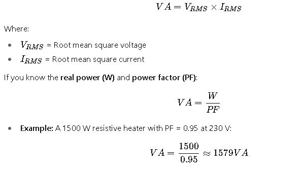
This ensures the supply and wiring are properly rated.
Three-Phase System
For three-phase systems, the apparent power depends on line voltage (VL) and phase voltage (VP):
Formula for Three-Phase, Balanced Load:
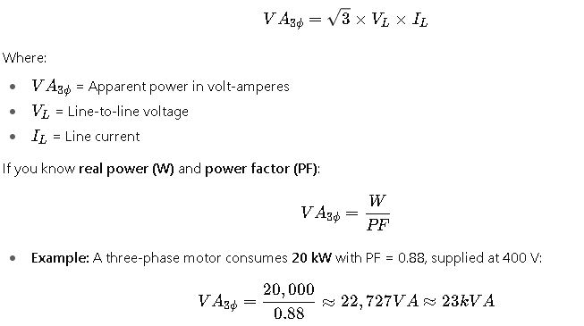
This formula ensures proper transformer and conductor sizing.
Tables for Three-Phase Systems
Table 4: Common Three-Phase Voltages and VA Ratings
| Line Voltage (V) | Current (A) | Apparent Power (VA) |
|---|---|---|
| 208 V | 5 A | 1.8 kVA |
| 208 V | 10 A | 3.6 kVA |
| 208 V | 20 A | 7.2 kVA |
| 230 V | 5 A | 2 kVA |
| 230 V | 10 A | 4 kVA |
| 230 V | 20 A | 8 kVA |
| 400 V | 5 A | 3.46 kVA |
| 400 V | 10 A | 6.93 kVA |
| 400 V | 20 A | 13.86 kVA |
| 480 V | 10 A | 8.31 kVA |
| 480 V | 20 A | 16.62 kVA |
| 480 V | 50 A | 41.55 kVA |
These tables are vital references for engineers designing industrial and commercial installations.
Real-World Application 3: Data Center Power Planning
Problem:
A data center has 50 servers, each rated at 600 W, supplied by a three-phase 400 V system, with an average power factor of 0.9. Determine the required UPS VA rating.
Solution:
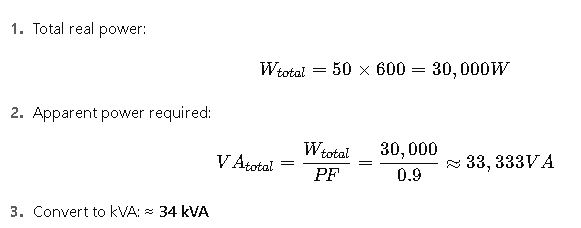
Answer:
The UPS should be rated ≥ 34 kVA. For redundancy and safety margin, a 40–45 kVA UPS is recommended.
Real-World Application 4: Renewable Energy System Sizing
Problem:
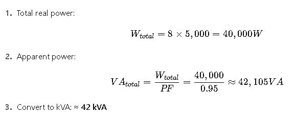
A small solar farm has inverters rated at 5 kW each with a power factor of 0.95. The system voltage is 230 V, single-phase. Calculate the total VA if 8 inverters are installed.
Solution
Answer:
The AC bus and protective devices must be rated for at least 42 kVA.
Extended Considerations for Volts to VA Calculations
- Derating Factors:
- Ambient temperature, conductor insulation, and harmonics can require oversizing.
- IEC and NEC standards provide guidance for derating transformers and UPS.
- Non-linear Loads:
- Devices like PCs, LED drivers, and variable frequency drives draw non-sinusoidal currents.
- True VA may exceed calculations using RMS current, so always consider apparent power for sizing.
- Efficiency Calculations:
- Transformers and UPS units have efficiency losses.
- Effective real power delivered:
Where η= efficiency (0–1).
- Harmonics and THD (Total Harmonic Distortion):
- High THD can increase apparent power requirements.
- Oversize VA by 10–20% for loads with significant harmonics.
Table 5: Reference VA Values for Common Electrical Devices
| Device | Voltage (V) | Current (A) | Power Factor | Apparent Power (VA) |
|---|---|---|---|---|
| Desktop Computer | 230 | 2 | 0.8 | 575 VA |
| Laptop Charger | 120 | 1 | 0.9 | 133 VA |
| LED Lighting (Office) | 120 | 5 | 0.95 | 632 VA |
| Air Conditioner (Residential) | 230 | 10 | 0.85 | 2.35 kVA |
| Industrial Motor 5 HP | 400 | 12 | 0.88 | 8.3 kVA |
| Server Rack (5 Servers) | 230 | 15 | 0.9 | 3.83 kVA |
These references are crucial when designing systems with multiple devices to avoid under-sizing or overloading.

