DC: kW = V × I ÷ 1,000 | 1φ AC: kW = V × I × PF ÷ 1,000 | 3φ AC: kW = V × I × PF × √3 ÷ 1,000📊 Quick Reference Table
| Volts | Amps | Phase | PF | kW |
|---|---|---|---|---|
| 220 | 10 | 1φ | 0.90 | 1.98 |
| 240 | 20 | 1φ | 0.95 | 4.56 |
| 380 | 15 | 3φ | 0.85 | 8.39 |
| 415 | 30 | 3φ | 0.90 | 19.41 |
| 440 | 50 | 3φ | 0.85 | 32.39 |
| 480 | 100 | 3φ | 0.90 | 74.82 |
❓ Quick FAQ
Can I convert volts to kW with voltage alone?
No. You also need the current in amps and, for AC circuits, the power factor.
Why is the three-phase result higher?
The √3 factor (≈ 1.732) accounts for the additional power delivered by three phases.
Converting Volts to kW is not a simple prefix change — it requires two additional inputs: the current in amperes and, for AC circuits, the power factor. Voltage alone tells you the electrical “pressure,” but without knowing how much current flows and how efficiently the load converts apparent power into real power, you cannot determine the actual kilowatts. This page gives you a free Volts to kW calculator that handles DC, single-phase AC, and three-phase AC circuits, plus the exact formulas, reference tables, six fully worked examples, and a professional FAQ.
Whether you are sizing a breaker for a 415 V three-phase motor, checking the power draw of a 240 V water heater, or estimating the load on a 380 V industrial feeder, this guide walks you through the conversion step by step. Every formula is grounded in the physics defined by IEEE and IEC 60038, and every example uses real-world equipment ratings so you can verify your own calculations with confidence.
Volts to kW Conversion Table
The table below shows common voltage and current combinations you encounter on motor nameplates, panel schedules, and load studies — each converted to kilowatts for both single-phase and three-phase circuits. All values assume typical power factors (PF) as indicated.
| Voltage (V) | Current (A) | Phase | PF | kW | Typical Application |
|---|---|---|---|---|---|
| 120 | 15 | 1φ | 1.00 | 1.80 | US residential circuit (resistive load) |
| 220 | 10 | 1φ | 0.90 | 1.98 | Window A/C unit, small appliance |
| 230 | 20 | 1φ | 0.85 | 3.91 | EU single-phase heat pump |
| 240 | 30 | 1φ | 1.00 | 7.20 | Electric tankless water heater |
| 240 | 20 | 1φ | 0.95 | 4.56 | Split-phase oven element |
| 380 | 15 | 3φ | 0.85 | 8.39 | Small three-phase motor (5.5 kW) |
| 400 | 25 | 3φ | 0.88 | 15.24 | EU industrial compressor |
| 415 | 30 | 3φ | 0.90 | 19.41 | Industrial three-phase motor (15 kW class) |
| 440 | 50 | 3φ | 0.85 | 32.39 | Large pump or fan motor |
| 480 | 65 | 3φ | 0.90 | 48.64 | US MCC motor feeder |
| 480 | 100 | 3φ | 0.90 | 74.82 | Large VFD-driven motor |
| 600 | 40 | 3φ | 0.90 | 37.41 | Canadian industrial plant feeder |
| 1,000 | 20 | 3φ | 0.85 | 29.44 | MV motor starter fed at 1 kV |
Notice that the same voltage and current produce very different kW values depending on the phase configuration and power factor. A 415 V, 30 A load at PF 0.90 delivers 19.41 kW on three-phase but only 11.21 kW on single-phase — the √3 factor in the three-phase formula accounts for the extra power available when three current-carrying conductors share the work.
Formulas: How to Convert Volts to kW Step by Step
Unlike simple prefix conversions (such as kW to watts), converting volts to kilowatts requires you to know the current in amperes and, for AC circuits, the power factor. Below are the three formulas — one for each circuit type.
DC circuits
In a DC circuit there is no power factor because voltage and current are always in phase. You simply multiply voltage by current to get watts, then divide by 1,000 to convert to kilowatts.
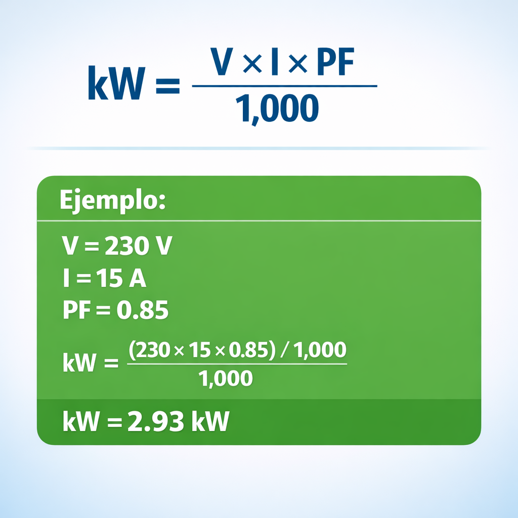
Single-phase AC circuits
In single-phase AC, the power factor (PF) represents the fraction of apparent power that does real work. A PF of 0.90 means 90% of the volt-ampere product is converted into real kilowatts; the remaining 10% circulates as reactive power, doing no useful work but still heating cables.
Three-phase AC circuits
For three-phase systems, an additional factor of √3 (approximately 1.732) enters the equation. This factor arises because three sinusoidal phases, each displaced 120°, collectively deliver √3 times the power of a single phase at the same line voltage and line current. Almost all industrial equipment — motors, compressors, chillers, large VFDs — operates on three-phase power, so this is the formula you will use most often on the plant floor.
Step-by-step: Convert 415 V, 30 A, 3φ, PF 0.90 to kW
- Identify the values: V = 415, I = 30 A, PF = 0.90, three-phase.
- Select the formula: kW = V × I × PF × √3 ÷ 1,000.
- Substitute: kW = 415 × 30 × 0.90 × 1.732 ÷ 1,000.
- Calculate step by step: 415 × 30 = 12,450 → 12,450 × 0.90 = 11,205 → 11,205 × 1.732 = 19,407.06 → 19,407.06 ÷ 1,000 = 19.41 kW.
- Verify context: 19.41 kW is consistent with a 15 kW (20 HP) motor drawing slightly more than its rated shaft power due to efficiency losses — the number makes sense.
DC vs. Single-Phase vs. Three-Phase — Formula Differences
Choosing the wrong formula is the single most common source of error when converting volts to kW. The table below summarizes the key differences so you can pick the right equation every time.
| Attribute | DC | Single-Phase AC | Three-Phase AC |
|---|---|---|---|
| Formula | V × I ÷ 1,000 | V × I × PF ÷ 1,000 | V × I × PF × √3 ÷ 1,000 |
| Power factor needed? | No (PF = 1 inherently) | Yes | Yes |
| √3 factor? | No | No | Yes (≈ 1.732) |
| Typical voltages | 12, 24, 48, 125, 250 V DC | 120, 220, 230, 240 V | 208, 380, 400, 415, 440, 480 V |
| Common loads | Batteries, solar panels, UPS DC bus | Residential appliances, lighting | Motors, compressors, industrial MCCs |
| Wiring | 2 conductors (+, −) | 2 conductors (L, N) + ground | 3 or 4 conductors (A, B, C, N) + ground |
| Standards | NEMA, IEEE C2 | NEC, IEC 60364 | NEC, IEC 60364, IEEE C37 |
If you ever doubt which formula applies, check the equipment nameplate or the panel schedule: it will state “1φ” or “3φ” (or “DC”). When the power factor is not listed, use 0.85 as a conservative default for motor loads or 1.0 for purely resistive loads like heaters and incandescent lamps. For LED lighting or electronic power supplies, 0.90–0.95 is a reasonable estimate unless the spec sheet says otherwise.
kW to Volts — Inverse Conversion
If you already know the kilowatts and need to find the voltage, rearrange the formulas:
| kW | Amps | Phase | PF | Required Voltage (V) |
|---|---|---|---|---|
| 5 | 25 | 1φ | 0.90 | 222 |
| 7.5 | 14 | 3φ | 0.85 | 364 |
| 15 | 25 | 3φ | 0.90 | 385 |
| 22 | 35 | 3φ | 0.88 | 413 |
| 37 | 55 | 3φ | 0.90 | 432 |
For the full inverse calculation, try our Amps to kW calculator, which also accepts kW as an input and solves for the missing variable.
6 Solved Examples — Real-World Volts to kW Problems
Example 1 — 240 V Water Heater (Single-Phase, Resistive)
Data: V = 240, I = 25 A, single-phase, PF = 1.00 (resistive).
Formula: kW = V × I × PF ÷ 1,000
Calculation: 240 × 25 × 1.00 ÷ 1,000 = 6.00 kW
6 kW matches a standard tankless water heater element. On a 240 V, 30 A circuit, this leaves 5 A of headroom — acceptable because the NEC 125% rule requires 25 × 1.25 = 31.25 A → a 40 A breaker is recommended for continuous loads.
Example 2 — 415 V Three-Phase Motor
Data: V = 415, I = 30 A, three-phase, PF = 0.88.
Formula: kW = V × I × PF × √3 ÷ 1,000
Calculation: 415 × 30 × 0.88 × 1.732 ÷ 1,000 = 18.97 kW
18.97 kW of input power. If the motor’s rated shaft output is 15 kW (20 HP) with an efficiency of 91%, the expected input is 15 ÷ 0.91 ≈ 16.48 kW — the measured 18.97 kW suggests the motor is carrying a heavier-than-rated load or the PF is slightly lower than 0.88. Worth investigating on site.
Example 3 — 220 V Window Air Conditioner (Single-Phase)
Data: V = 220, I = 10 A, single-phase, PF = 0.85.
Formula: kW = V × I × PF ÷ 1,000
Calculation: 220 × 10 × 0.85 ÷ 1,000 = 1.87 kW
1.87 kW is a typical rating for a 9,000–12,000 BTU window A/C unit. At this load, the monthly energy cost would be approximately 1.87 × 8 hours × 30 days × $0.12/kWh ≈ $53.86.
Example 4 — 380 V Industrial Compressor (Three-Phase)
Data: V = 380, I = 40 A, three-phase, PF = 0.85.
Formula: kW = V × I × PF × √3 ÷ 1,000
Calculation: 380 × 40 × 0.85 × 1.732 ÷ 1,000 = 22.38 kW
22.38 kW input matches a 22 kW (30 HP) screw compressor at full load. This is the value you put on your load schedule when sizing the transformer and main breaker for the plant.
Example 5 — 440 V Large Pump Motor (Three-Phase)
Data: V = 440, I = 65 A, three-phase, PF = 0.87.
Formula: kW = V × I × PF × √3 ÷ 1,000
Calculation: 440 × 65 × 0.87 × 1.732 ÷ 1,000 = 43.10 kW
43.10 kW input power. For a pump motor rated 37 kW (50 HP) at 90% efficiency, expected input is 37 ÷ 0.90 = 41.1 kW — the extra 2 kW could come from a slightly degraded power factor or bearing friction. Schedule a vibration analysis and PF correction check.
Example 6 — 48 V DC Battery Bank
Data: V = 48, I = 125 A, DC.
Formula: kW = V × I ÷ 1,000
Calculation: 48 × 125 ÷ 1,000 = 6.00 kW
6 kW from a 48 V DC battery bank — typical for a residential solar + storage system. At this discharge rate, a 10 kWh battery would last approximately 10 ÷ 6 ≈ 1.67 hours.
Volts to kW in Electric Motors
On a motor nameplate, the kW rating represents shaft output, but the volts-to-kW formula gives you electrical input. The difference is the efficiency loss inside the motor. If a motor nameplate says “15 kW, 415 V, 26 A, PF 0.86, η 91%,” here is what happens when you apply the volts-to-kW conversion:
Input kW = 415 × 26 × 0.86 × 1.732 ÷ 1,000 = 16.08 kW
Shaft output = 16.08 × 0.91 = 14.63 kW (which rounds to the rated 15 kW at nominal conditions).
The remaining 16.08 − 14.63 = 1.45 kW dissipates as heat inside the motor frame.
This distinction matters in every practical scenario. When you size cables and breakers, use the input kW (or, even better, the nameplate full-load amps). When you calculate mechanical shaft work — pump head, fan airflow, conveyor torque — use the output kW from the nameplate. Confusing the two leads to either undersized electrical infrastructure or overestimated mechanical capacity, both of which can cause failures.
For a deeper look at motor efficiency curves, see our Motor Efficiency Calculator. And if you need to go from amps directly to horsepower, try the Amps to HP calculator.
Quick Equivalences
Each equivalence below answers a specific search query directly. All three-phase values use PF = 0.85 (motor default) and all single-phase values use PF = 0.90 unless stated otherwise. The current assumed is printed in each card so you can adjust for your own circuit.
220 Volts to kW
1φ, 10 A, PF 0.90 → 1.98 kW
Common single-phase residential voltage in Latin America, Asia, and parts of Europe. Typical for window A/C units and small appliances.
240 Volts to kW
1φ, 20 A, PF 0.95 → 4.56 kW
US split-phase voltage for heavy appliances — ovens, dryers, water heaters. At 30 A, PF 1.0, you get 7.20 kW (resistive heater).
230 Volts to kW
1φ, 16 A, PF 0.90 → 3.31 kW
EU single-phase standard. Most residential circuits are protected at 16 A, giving roughly 3.3 kW of usable power.
380 Volts to kW
3φ, 15 A, PF 0.85 → 8.39 kW
380 V three-phase supply common in older industrial installations and many Asian/Latin American grids.
400 Volts to kW
3φ, 25 A, PF 0.88 → 15.24 kW
Standard IEC three-phase voltage across Europe and much of the world. Modern equivalent of the older 380 V standard.
415 Volts to kW
3φ, 30 A, PF 0.90 → 19.41 kW
Common in the UK, India, Australia, and the Middle East. Motors rated 15–22 kW typically draw 25–35 A at this voltage.
440 Volts to kW
3φ, 50 A, PF 0.85 → 32.39 kW
Heavy industrial voltage seen in large pump and fan motor installations. Older US/Canadian standard now mostly replaced by 480 V.
1,000 Volts to kW
3φ, 20 A, PF 0.85 → 29.44 kW
1 kV systems are the entry point of medium-voltage. Used for large motor starters and mine power distribution.
220 V to Kilowatts per Hour
Depends on amps and run time
“Kilowatts per hour” is a misnomer — the correct term is kilowatt-hours (kWh). For a 220 V, 10 A, PF 0.90 load running 1 hour: 1.98 kW × 1 h = 1.98 kWh of energy.
Volts to kW (General)
kW = V × I × PF (× √3 for 3φ) ÷ 1,000
You always need amps and power factor in addition to voltage. Without current, voltage alone cannot be converted to kW.
FAQ — Volts to kW Conversion
Can you convert volts to kW with voltage alone?
No. Voltage alone does not determine power. You must also know the current (amps) and, for AC circuits, the power factor. The formula is kW = V × I × PF ÷ 1,000 (single-phase) or kW = V × I × PF × √3 ÷ 1,000 (three-phase).
How many kW is 240 volts at 30 amps?
7.20 kW for a single-phase resistive load (PF = 1.0). Calculation: 240 × 30 × 1.0 ÷ 1,000 = 7.20 kW. If the load is a motor with PF 0.85, the result drops to 6.12 kW.
How do you convert 415 volts to kW?
For three-phase: kW = 415 × I × PF × 1.732 ÷ 1,000. Example: at 30 A and PF 0.90, you get 415 × 30 × 0.90 × 1.732 ÷ 1,000 = 19.41 kW.
What is the power factor and why does it matter?
Power factor is a number between 0 and 1 that indicates the fraction of apparent power (VA) that does real work (W). A PF of 0.85 means only 85% of the volt-ampere product becomes usable kilowatts. Motors, transformers, and other inductive loads typically have PFs between 0.80 and 0.95. Ignoring PF causes you to overestimate the real kW by 5–20%.
Why is √3 used in the three-phase formula?
√3 (approximately 1.732) arises from the 120° phase displacement between the three AC waveforms. It converts line voltage and line current into total three-phase power. Without this factor, you would underestimate the power by about 42%.
How many kW is 380 V at 40 A three-phase?
22.38 kW at PF 0.85. Calculation: 380 × 40 × 0.85 × 1.732 ÷ 1,000 = 22.38 kW — consistent with a 22 kW (30 HP) industrial motor at full load.
What does “220 volts to kilowatts per hour” mean?
It is a common but incorrect phrasing. The correct unit is kilowatt-hours (kWh), which measures energy, not power. To find kWh: first convert volts to kW using the formula, then multiply by the number of hours. For example, 220 V × 10 A × 0.90 ÷ 1,000 = 1.98 kW → 1.98 kW × 5 h = 9.90 kWh.
How do I find the power factor of my load?
Check the equipment nameplate — most motors and transformers list PF or cos φ directly. If unavailable, use a power analyzer (clamp-on meters like the Fluke 435-II display PF in real time). As a rule of thumb: resistive loads (heaters, incandescent lamps) have PF ≈ 1.0; motors have PF 0.80–0.92; LED drivers have PF 0.90–0.97.
What is the difference between kW and kVA?
kW is real power — the power that does actual work. kVA is apparent power — the product of volts and amps without accounting for phase angle. They are related by the power factor: kW = kVA × PF. A 100 kVA transformer at PF 0.85 delivers 85 kW of real power.
Is 440 V the same as 480 V?
No. 440 V and 480 V are distinct standard voltages. Historically, US systems used 440 V, but modern NEC standards specify 480 V as the nominal three-phase industrial voltage. Using a 440 V motor on a 480 V bus is usually acceptable within the ±10% tolerance per NEMA MG 1, but always verify the motor nameplate.
How do I convert volts to kW for a DC battery system?
Use kW = V × I ÷ 1,000. No power factor is needed. Example: a 48 V battery discharging at 100 A delivers 48 × 100 ÷ 1,000 = 4.80 kW.
Can I use this calculator for solar panel output?
Yes, for DC panels use the DC formula: kW = V × I ÷ 1,000. For the AC output of a grid-tied inverter, use the single-phase or three-phase formula with the inverter’s output voltage, current, and PF (typically 0.99–1.00 for modern inverters).
Related Conversions
- Amps to kW Calculator
- Amps to Watts Calculator
- Amps to VA Calculator
- Amps to HP Calculator
- Motor Efficiency Calculator
- Balanced and Unbalanced Load Calculation