Electrical engineering and electronics depend on accurate conversion between volts and amperes to ensure system safety. A volts-to-amperes calculator provides quick current determination, guiding engineers, technicians, electricians, and everyday equipment users.
🔄 Need the reverse calculation? If you need to convert from AMP to VOLT (the opposite direction of this page), use our dedicated AMP to VOLT calculator with full conversion tables, step-by-step examples, and engineering formulas.
Watts ↔ Amperes Calculator
Understanding the Relationship Between Volts and Amperes
- Voltage (V): Represents electrical potential difference, measured in volts.
- Current (I): Represents the flow of electric charge, measured in amperes (A).
- Power (P): The rate at which energy is transferred or consumed, measured in watts (W).
- Resistance (R): The opposition to current flow, measured in ohms (Ω).
The core relationship is described by Ohm’s Law and the Power Law.
Fundamental Formulas
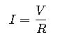
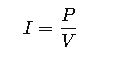
1. Ohm’s Law

Where:
- I= Current (Amperes, A)
- V= Voltage (Volts, V)
- R= Resistance (Ohms, Ω)
Common resistance values in electronics:
- Resistors: 1 Ω – 10 MΩ
- Household appliances: 5 – 100 Ω
- Heating elements: 10 – 1000 Ω
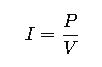
2. Power Law
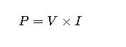
Where:
- P= Power (Watts, W)
- V= Voltage (Volts, V)
- I= Current (Amperes, A)
Rearranged to find current:
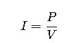
This is the most commonly used formula in volts-to-amperes calculators, especially when dealing with electrical appliances where wattage and voltage are known.
3. Combined Formula with Resistance
By combining Ohm’s Law and Power Law, we obtain:
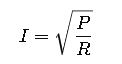
This is less commonly used in calculators but is critical in design and engineering analysis.
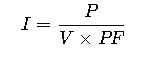
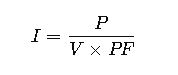
4. AC Power Formula (with Power Factor)
For alternating current (AC) systems:
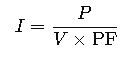
Where:
- PF = Power Factor (0 – 1).
Typical values: - Resistive loads (heaters, incandescent lamps): PF ≈ 1
- Inductive loads (motors, transformers): PF = 0.7 – 0.95
- Electronic devices with SMPS: PF = 0.6 – 0.9 (unless power factor corrected).
Extensive Volts to Amperes Conversion Tables
The following tables provide pre-calculated conversions for common voltages and power ratings. These values are essential for electricians and engineers working with real-world devices.
Table 1: Current from Voltage and Power (DC or AC with PF = 1)
| Voltage (V) | 10 W | 50 W | 100 W | 200 W | 500 W | 1000 W | 2000 W |
|---|---|---|---|---|---|---|---|
| 5 V | 2 A | 10 A | 20 A | 40 A | 100 A | 200 A | 400 A |
| 12 V | 0.83 A | 4.2 A | 8.3 A | 16.7 A | 41.7 A | 83.3 A | 167 A |
| 24 V | 0.42 A | 2.1 A | 4.2 A | 8.3 A | 20.8 A | 41.7 A | 83.3 A |
| 48 V | 0.21 A | 1.0 A | 2.1 A | 4.2 A | 10.4 A | 20.8 A | 41.7 A |
| 120 V | 0.08 A | 0.42 A | 0.83 A | 1.7 A | 4.2 A | 8.3 A | 16.7 A |
| 230 V | 0.04 A | 0.22 A | 0.43 A | 0.87 A | 2.2 A | 4.3 A | 8.7 A |
| 400 V | 0.025 A | 0.125 A | 0.25 A | 0.5 A | 1.25 A | 2.5 A | 5 A |
Table 2: Current from Voltage and Resistance (Ohm’s Law)
| Voltage (V) | 1 Ω | 5 Ω | 10 Ω | 50 Ω | 100 Ω | 500 Ω | 1000 Ω |
|---|---|---|---|---|---|---|---|
| 5 V | 5 A | 1 A | 0.5 A | 0.1 A | 0.05 A | 0.01 A | 0.005 A |
| 12 V | 12 A | 2.4 A | 1.2 A | 0.24 A | 0.12 A | 0.024 A | 0.012 A |
| 24 V | 24 A | 4.8 A | 2.4 A | 0.48 A | 0.24 A | 0.048 A | 0.024 A |
| 48 V | 48 A | 9.6 A | 4.8 A | 0.96 A | 0.48 A | 0.096 A | 0.048 A |
| 120 V | 120 A | 24 A | 12 A | 2.4 A | 1.2 A | 0.24 A | 0.12 A |
| 230 V | 230 A | 46 A | 23 A | 4.6 A | 2.3 A | 0.46 A | 0.23 A |
| 400 V | 400 A | 80 A | 40 A | 8 A | 4 A | 0.8 A | 0.4 A |
Table 3: AC Current with Power Factor (Example PF = 0.8)
| Voltage (V) | 100 W | 500 W | 1000 W | 2000 W | 5000 W |
|---|---|---|---|---|---|
| 120 V | 1.04 A | 5.21 A | 10.4 A | 20.8 A | 52.1 A |
| 230 V | 0.54 A | 2.7 A | 5.4 A | 10.8 A | 27.1 A |
| 400 V | 0.31 A | 1.56 A | 3.13 A | 6.25 A | 15.6 A |
Importance of Accurate Volts-to-Amperes Conversion
Errors in voltage-to-current calculations can cause:
- Overheating of wires and devices → risk of fire.
- Undersized fuses or breakers → nuisance tripping.
- Oversized protection devices → failure to protect equipment.
- Improper equipment selection → reduced efficiency and lifespan.
For compliance, engineers often refer to standards such as:
- IEC 60364 (Low-voltage electrical installations)
- NEC (NFPA 70) – National Electrical Code (USA)
- IEEE Std 141 – Electric Power Distribution for Industrial Plants
Practical Real-World Applications of Volts to Amperes Conversion
While tables and formulas are essential, their true value emerges when applied to real-world scenarios. Below are two detailed examples where volts-to-amperes calculations play a critical role in engineering and everyday life.
Case Study 1: Residential Water Heater Sizing
Scenario:
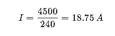
A homeowner in the United States installs a 4,500 W electric water heater. The supply is 240 V AC. The installer must determine the current draw to select the correct circuit breaker and wire gauge.
Step 1 – Formula:
Since resistive heating elements have a power factor ≈ 1, the formula simplifies to:
Step 2 – Substitution:
Step 3 – Engineering Considerations:
- NEC (National Electrical Code) requires that continuous loads be derated to 125%.
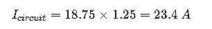
- The closest standard breaker rating above 23.4 A is 25 A, but NEC dictates using 30 A with 10 AWG copper wire.
Final Answer: The 4,500 W water heater draws 18.75 A, requiring a 30 A breaker and 10 AWG wiring.
Key Insight: This example illustrates how a simple volts-to-amperes calculation directly informs safe and compliant residential installations.
Case Study 2: Industrial Three-Phase Motor
Scenario:
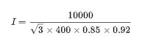
An industrial facility operates a 10 kW three-phase induction motor at 400 V AC, 50 Hz, with a power factor of 0.85 and an efficiency of 92%. The engineer must calculate the line current.
Step 1 – Formula (Three-Phase Current):
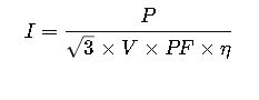
Where:
- P= Power (W)
- V = Line Voltage (V)
- PF= Power Factor
- η= Efficiency (decimal)
Step 2 – Substitution:
Step 3 – Calculation:
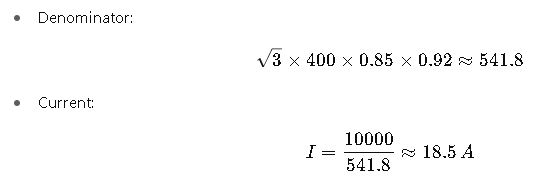
Final Answer: The motor draws 18.5 A per phase.
Engineering Implications:
- Cable sizing must consider ambient temperature and installation method (IEC 60364 guidance).
- Protection requires an overload relay calibrated slightly above 18.5 A.
- Inrush current may be 5–7× higher than full-load current, requiring motor-starting strategies (soft starters, VFDs).
Key Variables in Volts-to-Amperes Conversion
For precision, let’s expand on each influencing factor:
- Voltage (V):
- Residential supply: 120 V (North America), 230 V (Europe, Asia).
- Industrial supply: 400 V three-phase (Europe), 480 V three-phase (North America).
- Automotive: 12 V or 24 V DC.
- Current (I):
- Measured with ammeters or clamp meters.
- Critical for thermal protection and conductor sizing.
- Power (P):
- Resistive devices = Nameplate power ≈ true power.
- Inductive devices = Apparent power must be corrected by PF.
- Power Factor (PF):
- Determined by load type.
- Poor PF increases current draw without increasing useful power.
- Efficiency (η):
- Always less than 1.
- Motors: 90–98%.
- Transformers: 95–99%.
- Electronics: 70–95% depending on design.
Why Converting Volts to Amperes Matters
- Electrical Safety: Prevents overheating of cables and fire risks.
- Energy Efficiency: Avoids unnecessary current draw in industrial settings.
- System Design: Ensures proper selection of circuit breakers, contactors, fuses.
- Compliance: Meets legal standards like NEC (US), IEC (Europe), and IEEE