Use our VA to Volts Calculator to accurately convert apparent power into voltage for electrical systems. This tool simplifies complex conversions, essential for engineers working with single or three-phase power configurations.
🔄 Need the reverse calculation? If you need to convert from VOLT to VA (the opposite direction of this page), use our dedicated VOLT to VA calculator with full conversion tables, step-by-step examples, and engineering formulas.
VA to Volts Calculator
Single-phase:
V = VA / (A × PF)Three-phase:
V = VA / (√3 × A × PF)DC:
V = VA / AExtensive Table of Common VA-to-Volts Conversions
Below is a series of tables showing common scenarios: single-phase and three-phase systems, typical VA values, currents, and calculated voltages. These tables assist engineers in quick lookup and validation.
Single-Phase System (Power Factor = 1, Resistive Load)
| Apparent Power (VA) | Current (A) | Voltage (V) |
|---|---|---|
| 100 VA | 0.435 A | 230 V |
| 500 VA | 2.17 A | 230 V |
| 1,000 VA | 4.35 A | 230 V |
| 2,300 VA | 10.0 A | 230 V |
| 4,600 VA | 20.0 A | 230 V |
| 10,000 VA | 43.5 A | 230 V |
| 23,000 VA | 100.0 A | 230 V |
| 50,000 VA | 217.4 A | 230 V |
| 100,000 VA | 435 A | 230 V |
| 240 V examples: | ||
| 1,200 VA | 5.0 A | 240 V |
| 2,400 VA | 10.0 A | 240 V |
| 4,800 VA | 20.0 A | 240 V |
Three-Phase System (Balanced Load, Power Factor = 1)
Using line‑to‑line voltage of 400 V (Europe standard):
| Apparent Power (VA) | Line Current (A) | Voltage (V) |
|---|---|---|
| 1,000 VA | 1.44 A | 400 V |
| 5,000 VA | 7.21 A | 400 V |
| 10,000 VA | 14.4 A | 400 V |
| 25,000 VA | 36.1 A | 400 V |
| 50,000 VA | 72.2 A | 400 V |
| 100,000 VA | 144.3 A | 400 V |
| 200,000 VA | 288.7 A | 400 V |
Using line‑to‑line voltage of 480 V (North American industrial standard):
| Apparent Power (VA) | Line Current (A) | Voltage (V) |
|---|---|---|
| 10,000 VA | 12.0 A | 480 V |
| 25,000 VA | 30.0 A | 480 V |
| 50,000 VA | 60.0 A | 480 V |
| 100,000 VA | 120 A | 480 V |
| 200,000 VA | 240 A | 480 V |
These tables are essential for rapid estimation and verifying design against nominal voltage standards (e.g., 230 V, 400 V, 480 V), per IEC 60038 or IEEE Std 141.
Formulas for VA to Volts Calculations
1. Single‑Phase System
Basic formula:
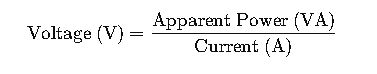
Where:
- Apparent Power (VA) is the product of voltage and current in AC circuits, combining real and reactive components.
- Current (A) is the magnitude of the AC current.
Variables explained:
- S – Apparent power in VA (volt-amperes).
- I – Electric current in amperes (A).
- V – Voltage in volts (V).
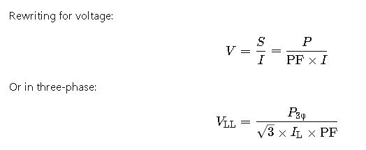
Alternate form:
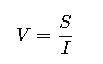
This form is particularly useful when both VA and current are known—common in load analysis or transformer rating contexts.
2. Three‑Phase System (Balanced Load)
Formula (line‑to‑line voltage, Δ or Y):
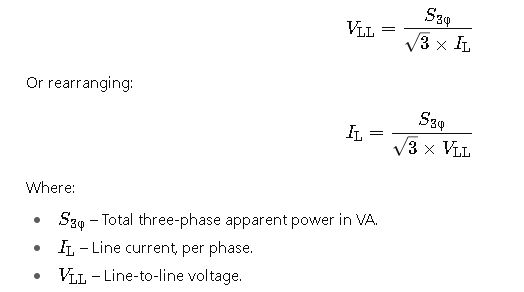
Variables:
- √3 (≈ 1.732) – Mathematical factor inherent in converting phase to line quantities in balanced three‑phase systems.
Use case: When designing or verifying three‑phase systems (e.g., motors, generators, distribution boards), this formula is essential.
3. Considering Power Factor (True General Formula)
When a power factor (PF) is involved (i.e., loads are not purely resistive):
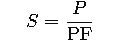
Where P is real (active) power in watts (W).
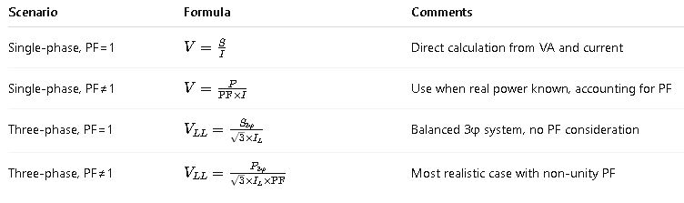
Summary of Key Formulas
Real‑World Application Examples
Here are two detailed, real‑world scenarios using these formulas in industrial or utility contexts.
Case Study 1: Designing a Single‑Phase UPS Feed for a Sensitive Load
Context:
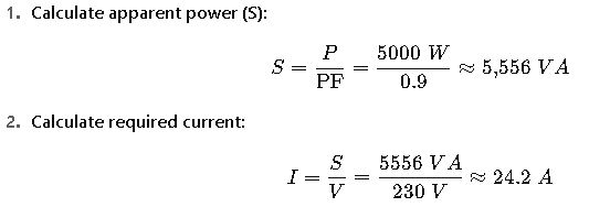
A medical facility requires a UPS (Uninterruptible Power Supply) that must deliver 5,000 W of real power at a power factor of 0.9 to critical equipment. The backup feed is single‑phase 230 V AC. Determine the required apparent power (VA) and current rating for the UPS, plus verify the voltage remains within tolerance.
Step‑by‑Step Solution:
- Calculate apparent power (S):
- Check voltage drop (assuming supply feeders, cable, etc.):
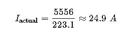
Let’s assume that supply cabling causes a 3% voltage drop under full load.
- Voltage drop: 230 V×0.03=6.9 V
- Effective voltage at load: 230−6.9=223.1 V
- Re‑calculate current slightly:
- UPS rating recommendation:
Choose a UPS rated at least:
- Apparent power: 6 kVA (to include some margin).
- Current: capable of supplying 25 A at 230 V.
Explanation: Real‑world engineering always builds in a safety margin (e.g., 10–25%) to handle overloads or future expansion. This case demonstrates applying formulas, voltage drop impact, and sizing an appropriate UPS.
Case Study 2: Sizing a Three‑Phase Transformer for an Industrial Motor
Context:
An industrial conveyor system requires a 50 kW three‑phase motor at a power factor of 0.85. The facility operates at 480 V line‑to‑line. You need to specify the transformer’s kVA rating and verify line current capacity.
Step‑by‑Step Solution:
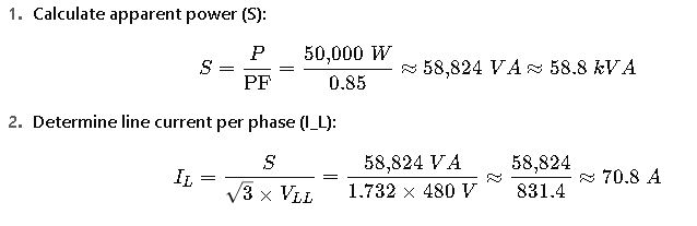
- Select transformer rating:
- Conservative engineering practice: choose a transformer at least 10–20% above actual need, therefore a 75 kVA transformer.
- Verify conductor and breaker rating:
Line current of ~71 A suggests:
- Conductors sized suitably (e.g., 90 °C copper wire rated for 80–90 A).
- Overcurrent protection (breaker or fuses) rated for, say, 80 A with appropriate coordination and short‑circuit characteristic.
Result: The selected 75 kVA three‑phase transformer will supply sufficient VA; line current is about 71 A.