This technical guide explains converting volt-ampere (VA) to amperes for AC and DC applications accurately.
Essential formulas, tables, and worked examples ensure correct current sizing for single-phase and three-phase systems.
VA-to-Amp Converter — Best Formula Reference and Quick Presets
Fundamental Concepts: Apparent Power, Real Power, and Current
Understanding the conversion from VA to amps requires precise definitions:
- Apparent power (S) measured in volt-amperes (VA) represents the product of RMS voltage and RMS current without regard to phase angle.
- Real or active power (P) measured in watts (W) is the portion of apparent power performing useful work; P = S × PF.
- Power factor (PF) is the cosine of the phase angle between voltage and current; PF ∈ (0, 1] for most industrial loads.
- Current (I) in amperes (A) is the electrical quantity we compute from VA given voltage and system configuration (single-phase vs three-phase).
Core Conversion Formulas
Below are the essential formulas used to convert apparent power (VA) into current (A) for common wiring scenarios.
Single-phase AC or DC (general apparent power)
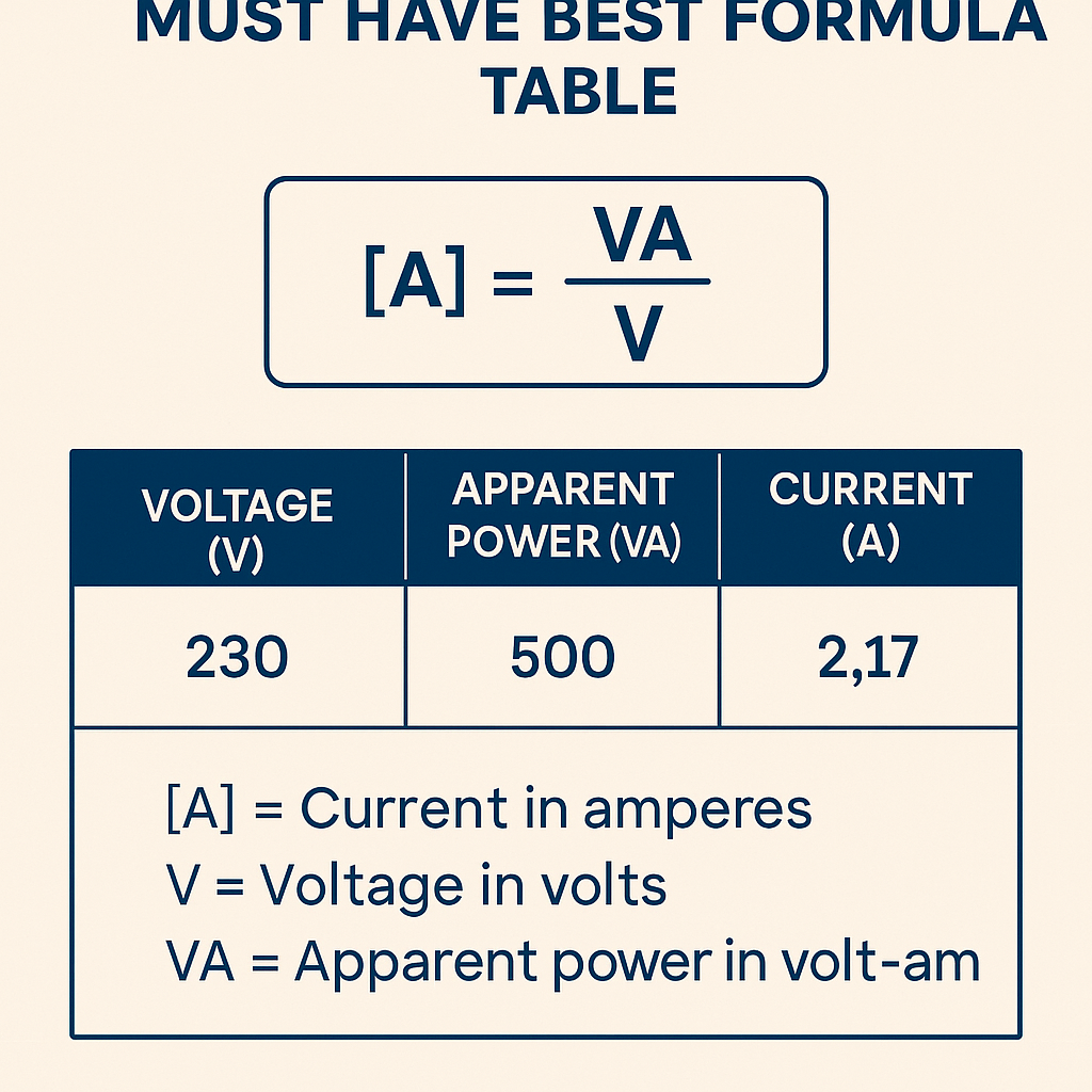
Formula: I = S / V
- S = apparent power in VA (or kVA × 1000).
- V = line-to-neutral or DC voltage in volts (V).
- I = current in amperes (A).
Typical values: V = 120 V (North America residential), V = 230 V (IEC standard), V = 240 V (some regions and appliances).
Single-phase using real power and power factor
Formula: I = P / (V × PF)
- P = real power in watts (W).
- PF = power factor (unitless, commonly 0.8–1.0 for many loads).
- Use this when only active power is specified or for energy billing alignment.
Three-phase balanced system (line-to-line voltage)
Formula: I = S / (√3 × V)
- S = apparent power in VA (for three-phase total, not per phase).
- V = line-to-line voltage in volts (V), e.g., 208 V, 400 V, 415 V, 480 V.
- √3 ≈ 1.732. Alternatively use 1.732 × V in the denominator for numeric computation.
- I = line current in amperes (A).
Three-phase using real power and power factor
Formula: I = P / (√3 × V × PF)
- P = total real power in watts (W).
- PF = power factor; include motor slip or correction factors when appropriate.
Variable Definitions and Typical Ranges
- S (VA): Apparent power; common device nameplate values range from tens of VA (small electronics) to hundreds of kVA (transformers).
- P (W): Active power; typical loads: lighting (10–100 W per fixture), HVAC compressors (several kW), industrial motors (several kW to MW).
- V (V): System voltage; residential: 120/240 V, international single-phase: 230 V, three-phase industrial: 208 V, 400–415 V, 480 V, 690 V.
- I (A): Current; wiring and protective devices are sized based on I with safety factors and codes applied.
- PF (unitless): Power factor; resistive heaters PF ~1.0, induction motors PF 0.7–0.95 depending on load and correction.
Extensive Lookup Table — Single-phase VA to Amps
The following table lists common apparent power values and computed currents for widely used single-phase voltages. Use this as a quick VA-to-amp converter reference.
| Apparent Power (VA) | Current @ 120 V (A) | Current @ 230 V (A) | Current @ 240 V (A) |
|---|---|---|---|
| 100 | 0.833 | 0.435 | 0.417 |
| 500 | 4.167 | 2.174 | 2.083 |
| 1,000 (1 kVA) | 8.333 | 4.348 | 4.167 |
| 2,000 (2 kVA) | 16.667 | 8.696 | 8.333 |
| 3,000 (3 kVA) | 25.000 | 13.043 | 12.500 |
| 5,000 (5 kVA) | 41.667 | 21.739 | 20.833 |
| 10,000 (10 kVA) | 83.333 | 43.478 | 41.667 |
| 15,000 (15 kVA) | 125.000 | 65.217 | 62.500 |
| 20,000 (20 kVA) | 166.667 | 86.957 | 83.333 |
| 30,000 (30 kVA) | 250.000 | 130.435 | 125.000 |
| 50,000 (50 kVA) | 416.667 | 217.391 | 208.333 |
Extensive Lookup Table — Three-phase VA to Amps
For three-phase balanced systems, currents are lower for the same VA due to the √3 factor. Table lists currents for common line voltages.
| Apparent Power (kVA) | Current @ 208 V (A) | Current @ 400 V (A) | Current @ 415 V (A) | Current @ 480 V (A) |
|---|---|---|---|---|
| 1 kVA | 2.776 | 1.443 | 1.391 | 1.203 |
| 5 kVA | 13.879 | 7.213 | 6.955 | 6.014 |
| 10 kVA | 27.758 | 14.426 | 13.909 | 12.028 |
| 25 kVA | 69.395 | 36.064 | 34.773 | 30.069 |
| 50 kVA | 138.789 | 72.128 | 69.546 | 60.139 |
| 100 kVA | 277.579 | 144.255 | 139.092 | 120.278 |
| 200 kVA | 555.158 | 288.510 | 278.183 | 240.556 |
Detailed Worked Example 1 — Single-phase Residential Load
Case: A 240 V electric water heater rated 3,600 W (resistive). Determine the current draw and recommended breaker sizing.
- Identify given data:
- P = 3,600 W (resistive, thus PF ≈ 1.0).
- V = 240 V (single-phase).
- Select formula: For resistive load with PF = 1, use I = P / (V × PF) = P / V.
- Compute:
- I = 3,600 W / 240 V = 15.0 A.
- Code and safety margin:
- NEC continuous load rule: if the load is continuous (defined as 3 hours or more), size branch-circuit conductor and breaker at 125% of full-load current: 15.0 A × 1.25 = 18.75 A.
- Round up to the next standard breaker size: 20 A.
- Choose conductor ampacity accordingly (12 AWG typical for 20 A in many jurisdictions, consult local code and derating factors).
- Result: The heater draws 15.0 A; a 20 A breaker and 12 AWG conductor are typical if continuous load rules allow.
Detailed Worked Example 2 — Three-phase Industrial Motor Load
Case: A three-phase motor nameplate lists 50 kVA apparent power at 400 V line-to-line and PF = 0.9. Determine line current and conductor considerations.
- Given:
- S = 50 kVA = 50,000 VA (apparent power).
- V = 400 V (line-to-line).
- PF = 0.9 (from nameplate).
- Choose formula for three-phase apparent power to current:
- I = S / (√3 × V)
- Compute denominator:
- √3 × V = 1.732 × 400 V = 692.8 V.
- Compute current using S:
- I = 50,000 VA / 692.8 = 72.129 A (line current based on apparent power).
- If only real power P were given, P = S × PF = 50,000 × 0.9 = 45,000 W. The current using P and PF would be:
- I = P / (√3 × V × PF) = 45,000 / (692.8 × 0.9) = 45,000 / 623.52 ≈ 72.129 A (same result, consistent).
- Apply code and thermal considerations:
- Motors often have inrush currents many times full-load current; protective device selection must consider locked-rotor currents and motor-starting characteristics per IEEE and IEC guidance.
- For continuous duty if applicable, apply 125% factor: 72.129 × 1.25 = 90.161 A. Choose next standard breaker/trip rating and conductor ampacity accordingly.
- Result: Line current ≈ 72.13 A; account for starting currents and apply code-required multipliers for conductor and protection sizing.
Worked Example 3 — UPS Sizing for Mixed Loads (added practical complexity)
Case: Data center rack draws 12 kW at 230 V single-phase with an aggregated PF of 0.95. Determine required UPS VA rating and input current.
- Given:
- P = 12,000 W.
- V = 230 V.
- PF = 0.95.
- Compute required apparent power S = P / PF:
- S = 12,000 / 0.95 = 12,631.58 VA ≈ 12.632 kVA.
- Compute input current on single-phase:
- I = S / V = 12,631.58 / 230 ≈ 54.92 A.
- Sizing decisions:
- Specify UPS with at least 12.7 kVA capacity (prefer an increment to cover harmonics and future load growth; e.g., 15 kVA).
- Breaker sizing: 54.92 A × 1.25 (continuous) = 68.65 A → select 70 A or 80 A protective device depending on local code and conductor ampacity.
- Result: Required UPS apparent rating ≈ 12.7 kVA, input current ≈ 54.9 A; select protective devices per continuous-load rules and manufacturer recommendations.
Practical Considerations for Accurate Conversion
- Always confirm whether the nameplate value is VA (apparent) or W (active). Misinterpreting the quantity is a common error.
- Check whether voltage listed is line-to-line or line-to-neutral when dealing with three-phase systems; using the wrong voltage leads to 1.732× error.
- Power factor matters: a low PF increases required current for the same real power and affects conductor heating and transformer loading.
- Derating: account for ambient temperature, conductor bundling, altitude, and insulation temperature ratings when sizing conductors.
- Motor starting and inrush: protective devices must allow safe starting; consider time-delay fuses, motor-starter curves, or soft starters.
- Harmonics: nonlinear loads increase RMS current without increasing real power; include harmonic distortion factors when calculating thermal stress.
- Measurement: use true-RMS meters and power analyzers for accurate measurement of VA and PF in non-sinusoidal systems.
Standards, Codes, and Authoritative References
Designers must apply recognized standards and local electrical codes when sizing equipment and protective devices. Key references include:
- NFPA 70, National Electrical Code (NEC) — requirements for conductor ampacity, breakers, and continuous load rules. See https://www.nfpa.org/NEC
- IEC 60364 — electrical installations of buildings; provides international wiring and safety guidance. See https://www.iec.ch/
- IEC 60038 — standard voltages, useful for selecting nominal voltages for tables and calculations. See https://webstore.iec.ch/ (search IEC 60038)
- IEEE Std 141 (Green Book) and IEEE Std 399 (Brown Book) — grounding, power system design, and industrial power considerations. See https://standards.ieee.org/
- NIST publications and measurement guidance for electrical metrology and true-RMS measurements. See https://www.nist.gov/
Best Practice Checklist for VA to Amp Conversions
- Verify nameplate units: VA vs W.
- Determine system configuration: single-phase or three-phase and line voltage reference.
- Obtain or estimate power factor; if unknown, conservatively assume PF ≤ 0.9 for motors or mixed loads.
- Apply appropriate formula:
- Single-phase: I = S / V or I = P / (V × PF).
- Three-phase: I = S / (√3 × V) or I = P / (√3 × V × PF).
- Apply continuous-load multipliers and rounding rules from applicable codes.
- Consider inrush, harmonics, derating, and environmental factors for final conductor and protective device selection.
- Document assumptions and perform peer review or simulation for critical installations.
Measurement and Instrumentation Guidance
To validate calculations on-site, use the following tools and procedures:
- True-RMS clamp meter to measure phase current accurately on non-sinusoidal loads.
- Power quality analyzer to measure apparent power S, real power P, and PF simultaneously.
- Verify voltages under load to use accurate V in calculations: measure line-to-line and line-to-neutral as required.
- Record harmonic spectrum if loads include inverters, variable-frequency drives (VFDs), or switch-mode power supplies; high harmonics change heating characteristics.
SEO and Keyword Optimization Notes (embedded relevance)
Frequently searched queries addressed in this article include: "VA to amp converter", "convert VA to amps", "VA to A table", "VA to amp formula", "apparent power to current", "single-phase VA to amps", and "three-phase VA to amps". Use the lookup tables and worked examples to answer immediate practical needs and support keyword-rich long-form content for engineers and electricians.
Rounding, Units, and Reporting Recommendations
- Report currents to three significant digits for engineering documentation; for procurement and breaker selection round up conservatively.
- Always state whether currents are line currents or per-phase values when documenting three-phase systems.
- When converting between kVA and VA, multiply kVA by 1,000. When converting between A and mA, multiply A by 1,000 as needed for instrumentation.
- Include a margin for future load growth; industry practice often recommends 10–25% spare capacity depending on criticality.
Common Pitfalls and How to Avoid Them
- Using line-to-neutral voltage for three-phase line-to-line calculations — results in a 1.732× error. Confirm voltage basis.
- Ignoring power factor — underestimating current leads to undersized conductors and overheating risks.
- Neglecting harmonics — harmonic currents increase RMS heating without increasing real power, requiring derating.
- Failing to apply continuous-load multipliers from code — can result in overloaded breakers or conductors.
Final Engineering Reminder
VA-to-amp conversion is straightforward mathematically but requires careful attention to system configuration, power factor, harmonics, and applicable codes. Always document assumptions, verify on-site, and follow authoritative standards for protection and conductor sizing.
Selected Further Reading
- NFPA 70 — National Electrical Code: https://www.nfpa.org/NEC
- IEC Standards and publications: https://www.iec.ch/
- IEEE Standards and recommended practices: https://standards.ieee.org/
- NIST Electrical Measurement Guidance: https://www.nist.gov/
- Technical overview on power factor and power relationships: https://www.energy.gov/ — search "power factor basics" for authoritative DOE materials.