Quickly determine whether a grounding electrode system conforms to NEC 250.50 and 250.52 requirements today.
This technical guide provides a rapid compliance checker, calculations, examples, references, and procedures for practitioners.
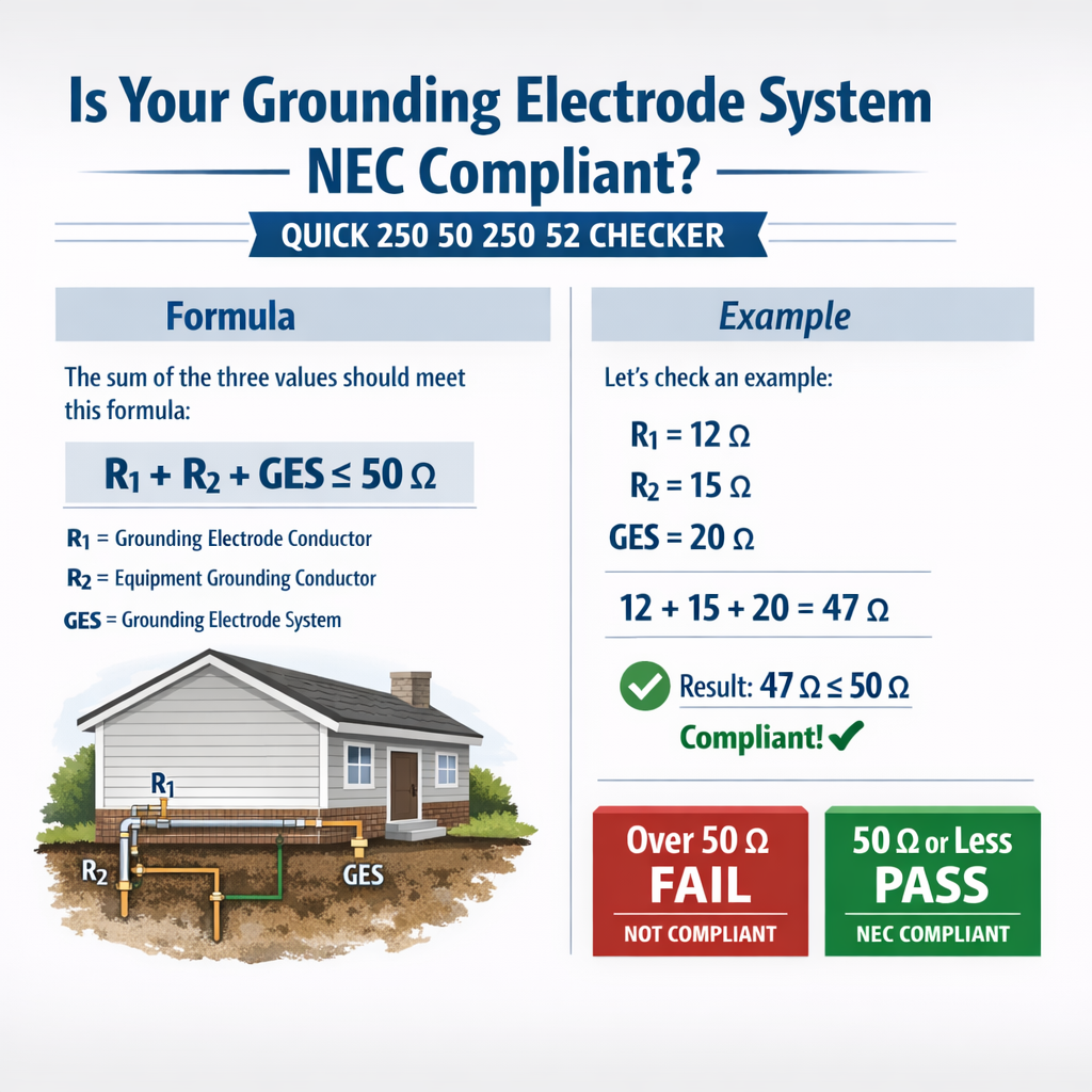
NEC 250.50 / 250.52 Grounding Electrode System Quick Compliance Checker
NEC scope and key mandates relevant to grounding electrode systems (250.50 & 250.52)
The NEC requires a grounding electrode system (GES) at electrical services and certain separately derived systems. Two provisions are central here: - NEC 250.50 establishes that when a grounding electrode is present it shall be part of the grounding electrode system and the system shall be installed per requirements. - NEC 250.52 enumerates acceptable grounding electrodes and clarifies minimum physical/electrical attributes for those electrodes.Practical compliance means verifying: electrode type(s) installed are listed in 250.52; the grounding electrode conductor (GEC) is sized, routed and connected per code; electrodes are bonded to form one system; accessible junctions and connector types meet 250.64 and 250.70; and measurement/verification shows continuity and effective connection to earth for fault-clearing purposes.Quick NEC compliance checklist: stepwise “250.50 / 250.52 Quick Checker”
Follow these steps in field inspections and documentation:- Identify installed electrodes and map them to NEC 250.52 categories.
- Confirm physical installation: embedment depth, length, spacing, and mechanical protection.
- Verify GEC sizing and routing to the service/disconnect (see NEC Table 250.66 for conductor sizing guidance).
- Ensure electrodes are bonded together to form a single GES (250.50) and bonded to grounded service neutral where required.
- Inspect connections: exothermic welds, listed clamps, or bolted joints with anti-oxidation measures.
- Measure continuity between electrodes and to the service equipment; perform earth resistance tests where required.
- Document measurements, equipment, soil conditions, and any corrective actions.
Minimum documentary evidence for compliance
- Photographs of electrode locations and connections.
- GEC size and route diagram with conductor types and protection.
- Results from continuity and earth-resistance measurements (date, instrument, test method).
- Reference to NEC edition used for inspection and any local amendments.
Common electrode types, NEC references, and typical performance
| Electrode Type | NEC Reference | Minimum installation note | Typical single-electrode resistance range (practical) |
|---|---|---|---|
| Concrete-encased electrode (Ufer) | 250.52(A)(3) | 20 ft of steel rebar or a 20 ft bare copper conductor embedded in concrete | 3–30 Ω (moist soils favorable) |
| Driven ground rod (copper or copper-clad) | 250.52(A)(5) | 8 ft typical; additional rods commonly required | 10–200 Ω (varies widely with soil resistivity) |
| Metal underground water pipe | 250.52(A)(1) | Minimum 10 ft in contact with earth; bonding to noncontinuously metal piping required | 5–50 Ω (depends on metallic continuity and length) |
| Ground ring | 250.52(A)(4) | Minimum 20 ft of bare conductor in a trench 2.5 ft deep | 2–30 Ω |
| Plate electrode | 250.52(A)(6) | Minimum 2.67 ft² of plate for copper; buried per manufacturer | 10–50 Ω |
Key measurement methods and formulas
Two essential calculation/formula families are used in GES evaluation: single-electrode approximate resistance modeling and the four-point (Wenner) soil resistivity method.Single driven rod resistance approximation
A widely used analytic approximation for a vertical rod of length L and radius d buried in soil of resistivity ρ is:R = ( ρ / (2 * π * L) ) * ( ln( (4 * L) / d ) − 1 )Explanation of variables and typical values:- R = resistance of single vertical rod to remote earth (ohms).
- ρ = soil resistivity (ohm·meters). Typical ranges: clay 10–100 Ω·m, loam 50–300 Ω·m, sand 200–2000 Ω·m.
- L = length of rod (meters). Typical rod: 8 ft = 2.4384 m.
- d = effective diameter of rod (meters). Typical driven rods: 5/8" ≈ 0.0159 m.
Four-point (Wenner) soil resistivity formula
When using the four-electrode Wenner method with equal probe spacing a and measured resistance R between potential and current electrodes:ρ = 2 * π * a * RExplanation:- ρ = apparent resistivity (ohm·meters).
- a = spacing between adjacent probes (meters).
- R = measured resistance (ohms) from the instrument after proper test procedure.
Typical soil resistivity table and expected 8-foot rod resistance
| Soil type | Typical ρ (Ω·m) | Estimated single 8 ft rod resistance R (Ω) | Notes |
|---|---|---|---|
| Moist clay | 20–50 | ≈7–18 | Good electrolytic contact; Ufer often low resistance. |
| Loam / silt | 50–200 | ≈18–70 | Moderate; multiple rods or ring often required for <25 Ω. |
| Dry sand / gravel | 200–1000 | ≈70–350 | Poor conductivity; chemical electrodes or long rings advisable. |
| Rock / fractured bedrock | >1000 | >350 | Very high resistance; specialized electrodes required. |
How to interpret measurements against NEC requirements
The NEC does not universally mandate a numeric earth resistance value for all installations in modern editions; rather, it requires that the grounding electrode system be installed in accordance with code provisions and be effective for the intended protective functions. Historically, a 25 Ω criterion was often used as a practical target; many jurisdictions still expect an earth resistance that facilitates reliable fault clearing and low touch potentials.Practical acceptance criteria used by inspectors and utilities:- Demonstrable continuity and low impedance path from service neutral to electrodes.
- Measured earth resistance that demonstrates a realistic path for fault current; many inspectors use 25 Ω as a guideline, though code enforcement varies.
- If a single electrode exceeds practical resistance thresholds, the addition of supplemental electrodes to reduce effective resistance is required in many utility practices and some local rules.
Detailed worked examples
Case 1 — Residential service with two widely spaced 8 ft rods
Scenario:- Single-family residence, service neutral bonded to GES at main service.
- Two driven copper-clad rods, each 8 ft (2.4384 m), spaced 20 ft apart.
- Measured/estimated soil resistivity ρ = 200 Ω·m (dry sandy loam).
- Rod diameter assumed d = 0.0159 m.
- ρ = 200 Ω·m
- L = 2.4384 m
- d = 0.0159 m
- ln( (4 * 2.4384) / 0.0159 ) ≈ ln(614.5) ≈ 6.421
- Bracket: 6.421 − 1 = 5.421
- Denominator: 2 * π * 2.4384 ≈ 15.32
- R_single ≈ (200 / 15.32) * 5.421 ≈ 13.06 * 5.421 ≈ 70.8 Ω
- R_total ≈ 35.4 Ω — above common 25 Ω target used by many AHJs.
- To meet lower resistance targets, options include adding additional rods at adequate spacing, installing a ground ring, using a concrete-encased electrode (Ufer), or employing chemical electrodes.
- Documentation: record soil resistivity measurement and instrument used; if GES must meet a numeric criterion, design additional electrodes accordingly.
Case 2 — Commercial building with concrete-encased electrode (Ufer)
Scenario:- Commercial building with foundation slab containing 20 ft of #4 rebar tied to a Ufer electrode.
- Soil resistivity ρ estimated at 50 Ω·m (moist clay/loam).
- Equivalent conductor length L = 20 ft = 6.096 m. Use approximate rod-like formula for a long conductor; effective diameter d ≈ 0.016 m.
- 4 * L / d ≈ (24.384 / 0.016) = 1524 → ln ≈ 7.328
- Bracket: 7.328 − 1 = 6.328
- Denominator: 2 * π * 6.096 ≈ 38.315
- R ≈ (50 / 38.315) * 6.328 ≈ 1.304 * 6.328 ≈ 8.26 Ω
- R ≈ 8.3 Ω — well below common 25 Ω guideline and excellent for fault current dissipation and touch potential mitigation.
- Ufer electrodes are frequently the most effective single electrode for commercial slabs in moderate soils.
Field measurement protocols and instrument considerations
Use calibrated instruments and recognized test methods. Typical steps:- Verify continuity between all electrodes and service neutral with low-impedance testers (bond testers) prior to earth-resistance tests.
- Perform Wenner four-pin resistivity testing for representative areas to obtain ρ.
- Measure single-electrode resistance using fall-of-potential method when practical; use three-point or clamp-on ground-resistance testers for systems where disconnecting the GEC is impractical (note limitations of clamp-on methods — they measure conductor loop impedance, not earth resistance directly, unless configured correctly).
- Record ambient conditions and probe spacing; repeat tests after rainfall for comparison if conditions are seasonally variable.
- Four-point resistivity meters and fall-of-potential ground testers are standard. Use instruments with traceable calibration.
- Clamp ground testers are helpful for quick checks but do not replace fall-of-potential measurements for electrode-to-earth resistance unless manufacturer guidance and test configuration are followed.
Practical corrective measures when resistance is high
If measurements indicate inadequate earth conductivity or GES effectiveness:- Add additional rods spaced widely (≥2× length recommended where practical), remembering diminishing returns when spacing is small.
- Install a ground ring or extend an existing ring connected to multiple electrodes.
- Create a concrete-encased electrode (Ufer) at foundations or install chemical/treated electrodes for long-term low resistance.
- Improve soil conductivity locally (e.g., conductive backfill or bentonite) following manufacturer recommendations and environmental regulations.
- Ensure all electrodes are bonded into a single GES and that connectors are listed and mechanically sound.
Normative references and authoritative resources
Consult these documents for code language, measurement standards, and in-depth analysis:- NFPA 70, National Electrical Code (NEC) — reference NEC sections 250.50, 250.52 and associated articles for exact code language.
- IEEE Std 81 — IEEE Guide for Measuring Earth Resistivity, Ground Impedance, and Soil Resistivity — methods for resistivity and ground system testing.
- NIST publications — for measurement traceability and calibration guidance.
- IEC 60364 series — international electrical installation standards, for non-US projects.
Summary of practical enforcement points for AHJs and engineers
- Verify electrode types installed correspond to those permitted by NEC 250.52.
- Confirm GEC sizing, routing, and connection comply with NEC rules and table-based sizing (reference Table 250.66 in the applicable NEC edition for conductor sizing).
- Ensure all electrodes are bonded to constitute a single, continuous GES in accordance with 250.50.
- Document measured earth resistivity, electrode resistance measurements, instrument calibration, and any remedial actions taken.
- When in doubt about numeric thresholds (e.g., 25 Ω), consult the AHJ and applicable local amendments to NEC.
- NFPA. NFPA 70: National Electrical Code. National Fire Protection Association. https://www.nfpa.org/NEC
- IEEE. IEEE Std 81-2012: Guide for Measuring Earth Resistivity, Ground Impedance, and Earth Surface Potentials. https://standards.ieee.org/standard/81-2012.html
- IEC. IEC 60364: Low-voltage electrical installations. https://www.iec.ch
- Manufacturers’ installation guides for listed clamps, exothermic weld materials, and chemical electrodes — consult manufacturer datasheets for product-specific requirements.
- Provide a printable checklist tailored to the NEC edition you specify.
- Run bespoke calculations for your site if you supply soil resistivity, electrode dimensions, and spacing.
- Generate labeled diagrams and a BOM for remedial electrode installations matching NEC compliance.