This guide explains calculating resistance (ohms) from length for grounding and bonding conductors precisely accurately.
Engineers and electricians require fast formulas, tables, and examples for compliant design and inspection work.
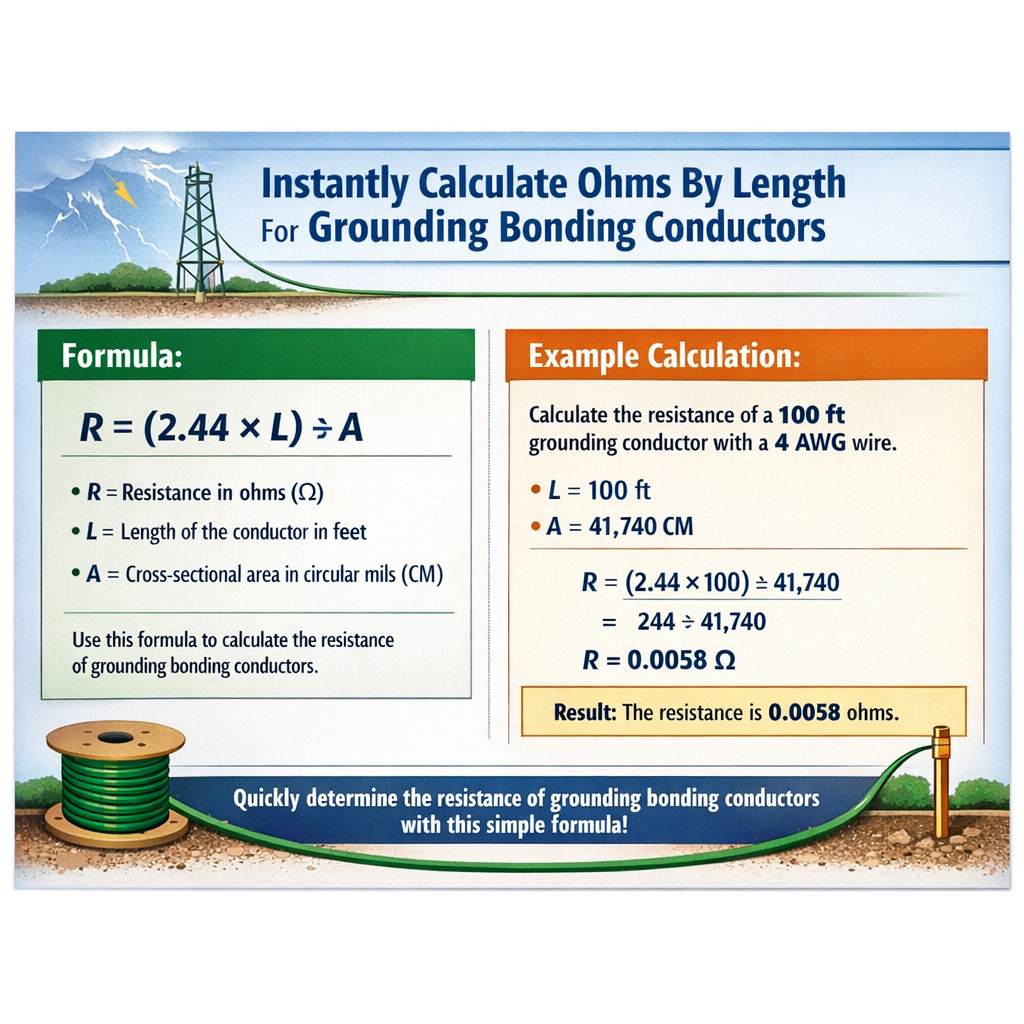
Grounding/Bonding Conductor Resistance Calculator (Ohms by Length)
Fundamental relationship for conductor resistance
Grounding and bonding conductor resistance is governed by the classical resistivity relation: R = ρ × L / A Where:- R = resistance (ohms, Ω)
- ρ = electrical resistivity of conductor material (ohm·m)
- L = length of the conductor (m)
- A = cross-sectional area of the conductor (m²)
- Copper: ρ ≈ 1.724 × 10^-8 Ω·m
- Aluminum (pure): ρ ≈ 2.826 × 10^-8 Ω·m
Temperature correction (practical accuracy)
Conductor resistance varies with temperature. Use a linear approximation: R(T) = R_ref × [1 + α × (T - T_ref)] Where:- R(T) = resistance at temperature T (°C)
- R_ref = resistance at reference temperature T_ref (commonly 20 °C)
- α = temperature coefficient of resistivity (per °C)
- Copper: α ≈ 0.00393 /°C (at 20 °C)
- Aluminum: α ≈ 0.0039–0.00403 /°C (commonly 0.0039 /°C used)
Units, geometry, and conversion essentials
Common field units are feet and AWG (American Wire Gauge) or meters and mm². Conversion links are essential for instant calculation. Cross-sectional area for a circular conductor: A = π × d² / 4 Where:- d = conductor diameter (m)
- A = area (m²)
- 1 ft = 0.3048 m
- 1 m = 3.28084 ft
Extensive standard resistance tables (common conductor sizes)
| AWG | Area (mm²) | Copper R (Ω/1000 ft) | Copper R (Ω/m) | Aluminum R (Ω/1000 ft) | Aluminum R (Ω/m) |
|---|---|---|---|---|---|
| 14 | 2.08 | 2.525 | 0.00829 | 4.147 | 0.01361 |
| 12 | 3.31 | 1.588 | 0.00521 | 2.610 | 0.00856 |
| 10 | 5.26 | 0.999 | 0.00328 | 1.642 | 0.00539 |
| 8 | 8.37 | 0.6282 | 0.00206 | 1.033 | 0.00339 |
| 6 | 13.30 | 0.3951 | 0.00130 | 0.649 | 0.00213 |
| 4 | 21.15 | 0.2485 | 0.00082 | 0.408 | 0.00134 |
| 2 | 33.62 | 0.1563 | 0.00048 | 0.257 | 0.00084 |
| 1 | 42.41 | 0.1239 | 0.00041 | 0.203 | 0.00066 |
| 1/0 | 53.48 | 0.09828 | 0.00033 | 0.161 | 0.00053 |
| 2/0 | 67.43 | 0.07798 | 0.00026 | 0.1278 | 0.00042 |
| 3/0 | 85.01 | 0.06187 | 0.00020 | 0.1014 | 0.00033 |
| 4/0 | 107.2 | 0.04904 | 0.00016 | 0.0806 | 0.00026 |
- Copper resistivity = 1.724×10^-8 Ω·m; Aluminum resistivity = 2.826×10^-8 Ω·m at 20 °C.
- Ω/1000 ft values are useful for US practice; Ω/m values provide SI convenience.
- Values shown rounded to typical commercial presentation precision.
Metric conductor table (common mm² sizes)
| Area (mm²) | Copper R (Ω/km) | Copper R (Ω/m) | Aluminum R (Ω/km) | Aluminum R (Ω/m) |
|---|---|---|---|---|
| 1.5 | 11.49 | 0.01149 | 18.83 | 0.01883 |
| 2.5 | 6.896 | 0.00690 | 11.30 | 0.01130 |
| 4 | 4.310 | 0.00431 | 7.064 | 0.00706 |
| 6 | 2.873 | 0.00287 | 4.706 | 0.00471 |
| 10 | 1.724 | 0.00172 | 2.826 | 0.00283 |
| 16 | 1.077 | 0.00108 | 1.767 | 0.00177 |
| 25 | 0.6896 | 0.00069 | 1.131 | 0.00113 |
| 35 | 0.4926 | 0.00049 | 0.8080 | 0.00081 |
| 50 | 0.3448 | 0.00034 | 0.5652 | 0.00057 |
| 70 | 0.2469 | 0.00025 | 0.4047 | 0.00040 |
| 95 | 0.1816 | 0.00018 | 0.2980 | 0.00030 |
| 120 | 0.1437 | 0.00014 | 0.2359 | 0.00024 |
| 150 | 0.1150 | 0.00012 | 0.1888 | 0.00019 |
| 185 | 0.09334 | 0.00009 | 0.1533 | 0.00015 |
| 240 | 0.07187 | 0.00007 | 0.1181 | 0.00012 |
Instant calculation formulas and field shortcuts
For practical instant calculations, precompute resistances per unit length: R_per_m = ρ / A R_per_ft = R_per_m / 0.3048 Then: R = R_per_m × L_m or R = R_per_ft × L_ft If you maintain a small lookup for R_per_ft or R_per_m for the conductor sizes you commonly use, then calculating resistance for any length is multiplication only. Quick field algorithm:- Identify material (Cu or Al) and conductor size (AWG or mm²).
- Fetch R_per_length from table (Ω/ft or Ω/m).
- Multiply R_per_length by run length.
- Apply temperature correction if ambient or conductor temperature deviates from 20 °C.
Example of algebraic implementable formula
Given AWG size with area A (mm²), convert to m²: A_m2 = A_mm2 × 1e-6. Then: R (Ω) = (ρ × L_m) / A_m2 Expressed explicitly: R (Ω) = (1.724e-8 × L_m) / (A_mm2 × 1e-6) for copper.Grounding and bonding conductor specifics and regulatory context
Grounding electrode conductors, equipment grounding conductors, and bonding jumpers each have different sizing and performance expectations in codes and standards. Key regulatory and normative references:- NFPA 70: National Electrical Code (NEC) — sections relevant: 250.4, 250.66, 250.122, 250.56.
- IEEE Std 142 (Green Book) — grounding system design and conductor selection guidance.
- IEEE Std 80 — substation grounding design and resistance computations.
- IEC 60228 — conductors of insulated cables; cross-section standardization.
- NIST material property data for resistivity and temperature coefficients.
- NFPA (NEC) information: https://www.nfpa.org
- IEEE Xplore (standards summaries): https://ieeexplore.ieee.org
- NIST material data: https://www.nist.gov
- IEC standards information: https://www.iec.ch
- The NEC specifies conductor sizing for equipment grounding conductors based on overcurrent protective devices (NEC 250.122) rather than purely resistance limits.
- Grounding electrode conductor size (NEC 250.66) depends on the largest ungrounded service-entrance conductor and electrode type.
- For safety, many jurisdictions and industry practices aim for low system grounding resistance values (for example, ≤25 Ω to earth for a single electrode where possible), but code compliance and system design require comprehensive evaluation beyond a single resistance value.
Worked examples — complete development and detailed solutions
Example 1 — Copper grounding conductor resistance for a short bond
Problem statement: Calculate the DC resistance of a 50 ft copper grounding conductor sized 6 AWG at 20 °C. Then compute the resistance at 75 °C. Given:- Conductor: Copper, 6 AWG
- Length L = 50 ft
- From table: Copper R_per_1000ft for 6 AWG = 0.3951 Ω/1000 ft
- Reference temperature T_ref = 20 °C
- Target temperature T = 75 °C
- α_copper = 0.00393 /°C
- DC resistance at 20 °C: R = 0.019755 Ω (≈0.01976 Ω)
- DC resistance at 75 °C: R = 0.024023 Ω (≈0.02402 Ω)
Example 2 — Long aluminum grounding conductor for a remote grounding electrode
Problem statement: A grounding electrode conductor is to be installed with an 2/0 AWG aluminum conductor, run length 150 ft (one-way). Determine DC resistance at 20 °C and the adjusted resistance at −10 °C (cold climate). Use 2/0 Al area = 67.43 mm² and aluminum resistivity ρ = 2.826×10^-8 Ω·m. Use α_al = 0.0039 /°C. Given:- Conductor: Aluminum, 2/0 AWG
- Area A = 67.43 mm² = 67.43 × 10^-6 m²
- Length L = 150 ft = 45.72 m
- ρ = 2.826 × 10^-8 Ω·m
- T_ref = 20 °C, target T = −10 °C
- α = 0.0039 /°C
- DC resistance at 20 °C: R = 0.01916 Ω (one-way)
- DC resistance at −10 °C: R = 0.01691 Ω (one-way)
- For two-way fault loops, sum the two conductor resistances in the loop.
- Aluminum is significantly higher resistivity than copper; equivalent ampacity or resistance requires larger aluminum cross-section.
Practical considerations for grounding and bonding design
Designers must consider:- Loop resistance vs. electrode resistance: grounding electrode system resistance to earth and conductor interconnections both affect overall performance.
- Fault current magnitude and duration: thermal and mechanical effects on bonding conductors require compliance with ampacity and conductor temperature-rise rules.
- Corrosion and mechanical protection: aluminum often requires antioxidant compounds and proper terminations to mitigate galvanic corrosion at dissimilar-metal joints.
- Use of parallel conductors: parallel conductors halve or divide resistance only if equal and placed to share current; code-approved methods and connectors must be used.
Sizing vs. resistance — what code expects
The NEC primarily prescribes grounding and bonding conductor sizes by function and ampacity relationships, not a single numeric maximum resistance. Typical practice:- Use NEC tables for equipment grounding conductor sizing (NEC 250.122).
- Size grounding electrode conductors per NEC 250.66 (based on largest ungrounded service conductor and reference tables).
- Evaluate grounding system resistance goals (e.g., ≤25 Ω for single electrode) but follow comprehensive site-specific design for safety.
Accuracy, measurement, and verification
When validating calculated resistances with measurements, remember:- Clamp-on DC resistance meters give high convenience for large conductors but must be validated for accuracy.
- Four-terminal (Kelvin) measurements eliminate contact resistance and are the most accurate for short conductors.
- Megger or earth resistance testers (fall-of-potential) are used for grounding electrode system resistance to earth, which is different than conductor DC resistance.
Reference standards and authoritative sources
For normative procedures and deeper design rules consult:- NFPA 70, National Electrical Code — available from NFPA: https://www.nfpa.org
- IEEE Std 142 (Green Book) — grounding of industrial and commercial power systems: https://ieeexplore.ieee.org
- IEEE Std 80 — guide for safety in substation grounding: https://ieeexplore.ieee.org
- IEC 60228 — conductors of insulated cables (cross-section classification): https://www.iec.ch
- NIST material properties — reference data for electrical resistivity and temperature coefficients: https://www.nist.gov
Best practices checklist for instant field calculations
- Keep a laminated quick-reference table for the conductor sizes you install frequently (Ω/ft and Ω/m).
- Always confirm conductor material and temperature before final risk assessment.
- Apply temperature correction when conductor runs may operate significantly above or below 20 °C.
- Document calculations and measurement results for inspection and maintenance records.
- When in doubt, oversize for lower resistance and improved safety margins, and verify per code requirements.
Quick mnemonic for rapid mental math
If you remember a conductor’s Ω/1000 ft value, multiply by length in feet and divide by 1000: R ≈ (Ω_per_1000ft × length_ft) / 1000 Or with meters: R ≈ (Ω_per_km × length_m) / 1000 This reduces most field calculations to two arithmetic operations.Final technical notes
Accurate grounding and bonding conductor resistance calculations depend on correct material properties, precise cross-sectional area, and temperature. For safety-critical systems, complement calculation with measurements, and follow applicable code requirements (NEC, IEEE, IEC). Use the tables above or compute on-demand using R = ρ × L / A and remember to perform temperature adjustments when conditions differ from the reference. References:- NFPA 70: National Electrical Code — authoritative code for electrical installations in the United States.
- IEEE Std 142 — The Green Book: grounding of industrial and commercial power systems.
- IEEE Std 80 — Guide for Safety in AC Substation Grounding.
- IEC 60228 — Standard on conductor cross-section classes.
- NIST — material properties database for precise resistivity and temperature coefficients.