This article explains instant electrical bonding jumper sizing for MBJ supply and load sides accurately.
Tool calculates conductor sizes, fault current ratings, temperature correction, and installation constraints quickly and reliably.
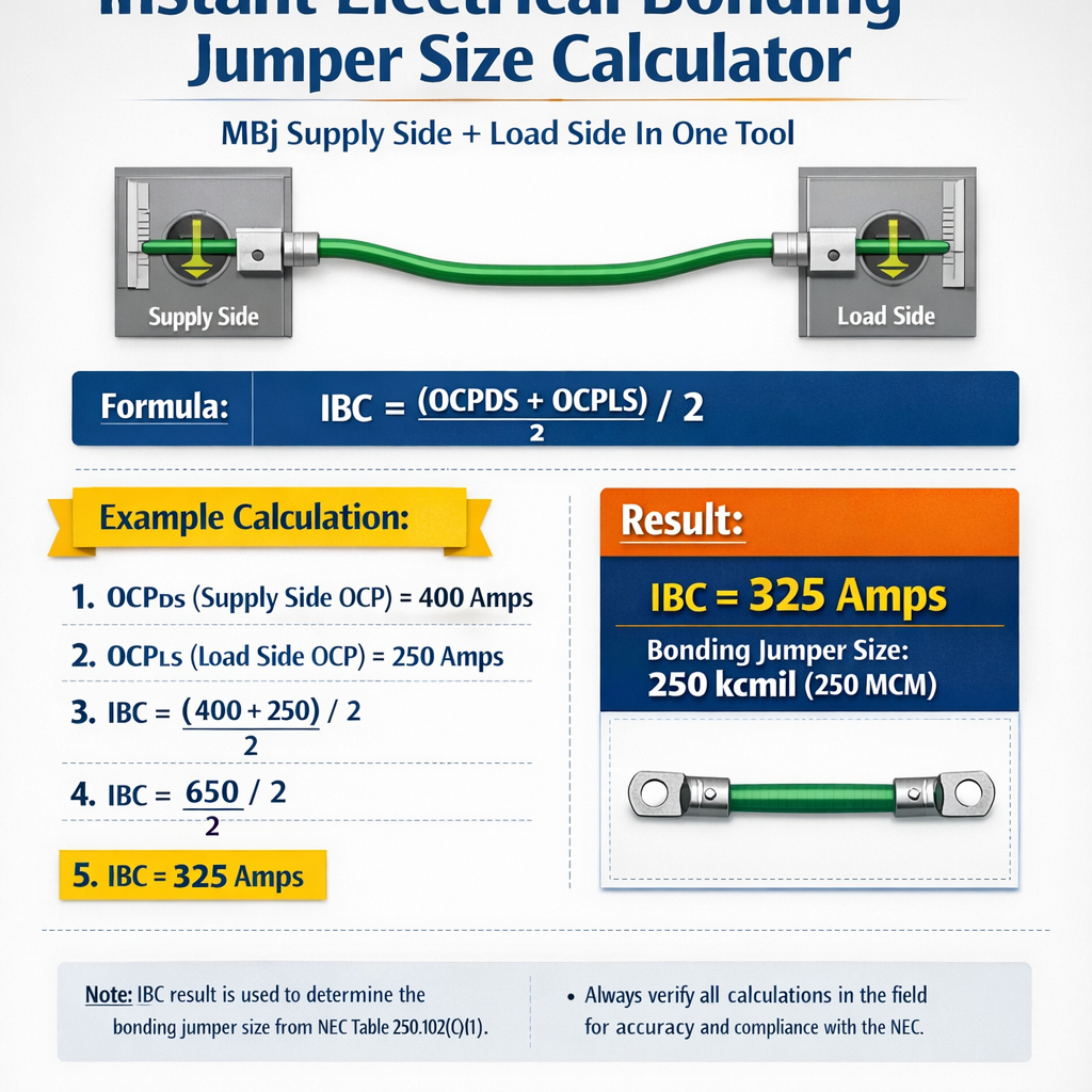
Instant Electrical Bonding Jumper Size Calculator (Main, Supply-Side and Load-Side – Cross-Section in mm²)
Scope and purpose of an instant MBJ sizing calculator
An Instant Electrical Bonding Jumper Size Calculator centralizes rules, adiabatic checks and code minima into a single decision workflow for both supply side and load side bonding jumpers. The primary purpose is to determine a safe cross‑sectional area (S) for the bonding jumper that meets thermal withstand for fault clearing, mechanical requirements, and code minimums without over‑sizing that increases cost and installation complexity.
Definitions and roles: MBJ, supply side, load side
- Main Bonding Jumper (MBJ): the conductor (or assembly of conductors) that connects the grounded service conductor or supply neutral to the earthing electrode system at the service equipment or transformer enclosure. It establishes the primary equipotential between system neutral and earth.
- Supply side MBJ: the MBJ located at the service or transformer primary point of connection where the supply neutral/grounded conductor is bonded to the earthing electrode conductor and local earth. Often subject to mandatory minimum sizing requirements in national codes.
- Load side bonding jumper: bonding conductors downstream of the main bonding point that connect exposed conductive parts and equipment enclosures to the protective earthing network. These must be sized to withstand prospective fault currents for the expected clearing time.
Design principles used by the calculator
The sizing calculator implements two principal design checks:
- Adiabatic short‑circuit thermal check (I^2t energy withstand): ensures the conductor cross‑section S provides sufficient thermal mass to survive the fault duration without melting or excessive thermal damage.
- Continuous current and mechanical checks: verifies the selected conductor can carry intentional or continuous equipotential currents (e.g., transfer currents, test currents) and that terminations, lugs and mechanical anchorage meet strength requirements.
Regulatory baseline and mandatory minima
National and regional standards set mandatory minima that any automated tool must check before recommending a smaller cross section.
- NFPA 70 (NEC) Article 250 — Equipment bonding and size rules (see Table 250.66 and 250.122) — link: https://www.nfpa.org/
- BS 7671 (IET Wiring Regulations) — Regulation 543 and guidance for main earthing/bonding conductors — link: https://www.theiet.org/
- IEC 60364 series — Earthing and equipotential bonding principles — link: https://www.iec.ch/
- IEEE Std 142 (Green Book) — Grounding of Industrial and Commercial Power Systems — link: https://standards.ieee.org/
Core formula: adiabatic conductor sizing
The calculator uses the standard adiabatic short‑circuit equation:
Explanation of variables and typical values:
- S = required conductor cross‑sectional area (mm²)
- I = maximum prospective fault current (A) contributing to the bonding conductor (symmetrical or RMS depending on code; use RMS for energy calculations) — typical values: 5,000 A to 50,000 A depending on transformer and supply impedance.
- t = fault duration until interruption (s) — typical protection device clearing times: 0.1 s (fast breakers), 0.5 s (typical fuse/relay clearing), 1.0 s (longer coordination).
- k = material and temperature dependent constant (sqrt(2 × ρ × Δθ) consolidated) — typical recommended values: copper ≈ 115, aluminium ≈ 95 (use code‑specific tables). See references: IEC/BS/NEC guidance.
Note: The calculator must be configured to use the k value consistent with the selected standard and conductor insulation/initial temperature assumptions. For example, BS 7671 and IEC references include tables for k corresponding to different initial conductor temperatures and material conditions.
Detailed algorithm used in the tool
- Input collection:
- Conductor material (copper or aluminium).
- Prospective fault current at bonding connection point (Isc) — input symmetrical RMS value or phase-to-earth value as required.
- Expected protection device clearing time (t).
- Desired design standard (NEC, BS 7671, IEC) to apply code minima.
- Ambient and initial conductor temperature, insulation type, grouping & correction factors.
- Adiabatic calculation:
Compute raw S using S = I × sqrt(t) / k
- Apply mechanical/ampacity checks:
- Verify selected S meets continuous current requirements (if the bonding conductor is expected to carry continuous currents); apply correction factors for ambient temperature and grouping per chosen standard.
- Consider mechanical robustness: minimum conductor diameter for lugs, supports and fault mechanical energy.
- Check standard minima:
Compare computed S to mandatory minimums from the selected code. Where code requires a larger minimum, override with code minimum.
- Round up to standard conductor sizes and recommend copper/aluminium equivalent.
- Output full compliance report, showing calculations, assumed k, protection device curve, and code references.
Correction factors and special cases
Real installations require adjustments to the basic adiabatic result when additional thermal/mechanical effects are present.
- Parallel conductors: where conductors are installed in parallel to increase current capacity, the tool distributes fault current per manufacturer and standard guidance and recalculates S for each parallel run.
- Grouping and ambient temperature: apply multiplicative correction factors to continuous current checks. For short‑circuit adiabatic energy, initial temperature affects k rather than a multiplicative factor.
- Connections and terminations: reduction for termination size — ensure lugs and bolts are rated for computed fault current and mechanical forces.
- Earthing electrode conductor length and impedance: verify that local electrode impedance does not create unexpected voltage rises; verify equipotential bonding paths remain low impedance.
Common k values and initial/final temperatures (typical)
Typical k constants used by the calculator (selectable per standard):
| Material | Typical k value | Initial temperature (°C) | Final limiting temperature (°C) | Reference standard |
|---|---|---|---|---|
| Copper (annealed) | 115 | 70 | 160 | IEC/BS typical table |
| Aluminium | 95 | 70 | 160 | IEC/BS typical table |
| Copper (lower initial temp) | 143 | 20 | 160 | Some references use k=143 for initial 20°C |
Extensive tables: common prospective fault currents and resulting copper sizes
The following precomputed table is useful for quick lookup when designing with copper bonding jumpers. These values assume k = 115 and t = 0.5 s unless otherwise noted. Sizes are rounded up to nearest standard metric conductor size.
| Prospective fault current (A) | t = 0.2 s (mm²) | t = 0.5 s (mm²) | t = 1.0 s (mm²) | Recommended standard size (mm²) for t=0.5s |
|---|---|---|---|---|
| 5,000 | 39 | 61 | 86 | 70 |
| 10,000 | 78 | 123 | 173 | 150 |
| 15,000 | 117 | 184 | 259 | 240 |
| 20,000 | 156 | 245 | 346 | 300 |
| 25,000 | 195 | 306 | 433 | 400 |
| 30,000 | 234 | 367 | 520 | 500 |
| 40,000 | 312 | 490 | 693 | 630 |
| 50,000 | 390 | 613 | 866 | 800 |
Notes on the table above
- These precomputed values use S = I × sqrt(t) / k with copper k = 115.
- Round up to the nearest commercially available conductor cross section (e.g., 16, 25, 35, 50, 70, 95, 120, 150, 185, 240, 300, 400, 500, 630, 800 mm²).
- Always verify against mandatory minima from the selected standard (NEC, BS 7671, local regulations).
Examples — real case studies with complete development and solutions
Example 1: Supply side MBJ at a 400 A LV service (copper) — adiabatic sizing
Project scenario: A commercial building service transformer supplies a 400 A LV main. The utility short‑circuit calculation reports a prospective phase‑to‑earth fault current at the service neutral/earth point of 20,000 A (symmetrical RMS). Protection device clearing time at the service is estimated as 0.5 s. The installer chooses copper conductors and selects design code BS 7671 for minima.
Step 1 — Input values
- I = 20,000 A (prospective fault current)
- t = 0.5 s (estimated breaker clearing time)
- Material: Copper
- k = 115 (selected per BS/IEC typical table)
Step 2 — Apply adiabatic formula
Step 3 — Round to standard conductor size and apply code minima
- Nearest standard size > 122.99 mm² is 125 mm² (commonly 120 or 125; many catalogs list 120/125 mm²; choose 125 mm² or next standard 150 mm² if 125 not available).
- BS 7671 minimum main earthing conductor for 400 A service — verify code table; often main earthing conductor equals or exceeds certain minima. If code minimum is 25 mm² copper for smaller services, but because of fault energy the adiabatic result drives sizing to 125 mm²; adopt 125 mm².
Step 4 — Final verification
- Check terminations and lugs rated for 20 kA prospective current and mechanical forces.
- Check that earth electrode conductor routing provides low impedance path; consider paralleling if necessary for mechanical integrity.
Final recommended supply side MBJ: 125 mm² copper (rounded to nearest standard 150 mm² if necessary for availability), with all lugs and clamps rated for the prospective fault current and installed per BS 7671 guidance.
Example 2: Load side bonding jumper for large distribution board (copper) — specification and verification
Project scenario: A distribution board supplies several motor loads. The prospective fault current at the board’s metal enclosure is calculated as 10,000 A. The protective device at the board is a fused switch with typical clearing time estimated as 0.2 seconds. The bonding jumper connects the board enclosure to the local main earth bus.
Step 1 — Input values
- I = 10,000 A
- t = 0.2 s
- Material: Copper
- k = 115
Step 2 — Adiabatic check
Step 3 — Round to standard size and verify continuous current
- Rounded standard conductor size = 50 mm² copper (nearest typical commercial size above 38.89 mm²).
- Continuous current check: 50 mm² copper conductor continuous ampacity varies with installation method (e.g., >200 A depending on insulation and grouping). Usually sufficient for a bonding jumper that is not used as a distribution neutral.
Step 4 — Code minima
- Check NEC/BS minima: For equipment bonding conductors, code may require a minimum of 6 AWG (13 mm²) or larger depending on overcurrent protective device; the adiabatic result dominates and 50 mm² is acceptable.
Final recommended load side bonding jumper: 50 mm² copper, terminate with lugs rated for the prospective 10 kA and follow torque and installation requirements per manufacturer and code.
Additional verification: mechanical stress and conductor parallelism
Bonding jumpers can be subjected to tremendous electromagnetic forces during faults; the tool flags mechanical stress cases and recommends:
- Use of multiple parallel conductors or mechanically robust single conductors for high fault currents.
- Use of dedicated clamps and bolted connections with appropriate torque ratings.
- Provision for conductor routing to minimize unsupported spans and prevent whipping during fault; use of cable cleats rated for fault conditions.
Integration with protection coordination and system studies
For highest accuracy, the Instant MBJ calculator should be integrated with short‑circuit studies (IEC/IEEE) and protection coordination software. Inputs from a short‑circuit study give realistic prospective currents at the point of bonding; protection device curves (time‑current characteristic — TCC) provide actual clearing times instead of assumed values.
Recommended integration workflow
- Run system short‑circuit study to determine phase‑to‑earth prospective currents at each bonding point.
- Extract upstream and local protective device TCC to determine actual clearing times for each prospective fault level.
- Feed I and t values into the MBJ sizing calculator for each bonding node.
- Review outputs for both adiabatic S and continuous current checks; adjust conductor grouping or protection if necessary.
Installation considerations and best practices
- Use copper for MBJ when possible because of superior conductivity and mechanical robustness; aluminium requires larger cross sections and anti‑oxidation measures at terminations.
- Keep bonding jumper runs short and direct to minimize inductance and voltage rise during faults.
- Use properly rated lugs, bolts and washers (material compatibility and torque settings). Follow manufacturer torque values strictly.
- Document the calculated justification and include the short‑circuit study printouts, k constants, rounding rules and code references in the as‑built records.
- When paralleling conductors, ensure equal current distribution by using identical length and construction conductors and identical termination arrangements.
Standards, normative references and authority links
Key authoritative documents that the calculator references and cites in its compliance output:
- NFPA 70, National Electrical Code (NEC) — Article 250: Grounding and Bonding. https://www.nfpa.org/
- BS 7671 (IET Wiring Regulations) — Requirements for Electrical Installations. https://www.theiet.org/
- IEC 60364 series — Electrical installations of buildings. https://www.iec.ch/
- IEC 60909 (Short‑circuit currents in three‑phase AC systems) — methods to calculate prospective currents. https://www.iec.ch/
- IEEE Std 142 — Grounding of Industrial and Commercial Power Systems (Green Book). https://standards.ieee.org/
- Relevant manufacturer datasheets for lugs, cable cleats and connectors — consult suppliers for mechanical fault ratings.
Limitations and safety warnings
- The tool provides engineering guidance but does not replace formal stamping or approval by a qualified engineer in your jurisdiction. Always verify final selections with local code authority and project engineer.
- Prospective fault currents must be obtained from an up‑to‑date short‑circuit study including utility source impedance and transformer data.
- When in doubt, increase conductor size to provide mechanical robustness and future flexibility, especially for supply side main bonding jumpers.
Frequently used quick checks embedded in the calculator
- Minimum code size check — local regulation overrides adiabatic result if higher.
- Termination and lug rating check — do lugs have published mechanical/fault ratings for selected S?
- Parallel conductor balance check — is current distribution acceptable and are terminations symmetrical?
- Continuity and installation resistivity check — measure continuity after installation and compare to design values.
Practical recommendations for implementers and contractors
- Collect accurate inputs: conductor material, insulation type, ambient temperature, protective device characteristics, actual short‑circuit data, and code selection before running calculations.
- Use the calculator to produce printable compliance reports that list every assumption and calculation step for acceptance by inspectors and clients.
- Train electrical installers on MBJ installation best practices: tight and clean terminations, anti‑oxidation for aluminium, mechanical supports and correct torque application.
- For retrofit or seismic regions, consider mechanical strengthening and parallel redundant bonding routes to maintain earthing during long‑term degradation or mechanical damage.
Summary of key formulas used (HTML form) and typical numeric examples
Example: I = 20,000 A, t = 0.5 s, k = 115 → S = 20,000 × sqrt(0.5) / 115 = 122.99 mm² → select 125 mm² or 150 mm²
Example: I = 10,000 A, t = 0.2 s, k = 115 → S = 10,000 × sqrt(0.2) / 115 = 38.89 mm² → select 50 mm²
References and further reading
- NFPA 70, National Electrical Code — Official site and code purchase: https://www.nfpa.org/
- BS 7671: Requirements for Electrical Installations — The IET: https://www.theiet.org/
- IEC 60364 series and IEC 60909 for short‑circuit calculations: https://www.iec.ch/
- IEEE Std 142 — Grounding of Industrial and Commercial Power Systems: https://standards.ieee.org/
- IEC/BS technical guidance on adiabatic equation and k values — consult the specific clause in the standards for the k table used by your jurisdiction.
Using these methods, an Instant Electrical Bonding Jumper Size Calculator provides consistent, auditable sizing for both MBJ supply side and load side bonding jumpers, combining adiabatic energy checks, continuous current and code minima into a single, defensible recommendation suitable for detailed engineering documents.