This article provides a technical checklist and calculator for NEC 250 grounding and bonding requirements.
It includes formulas, tables, examples, and quick methods for service disconnect bonding conductor sizing requirements.
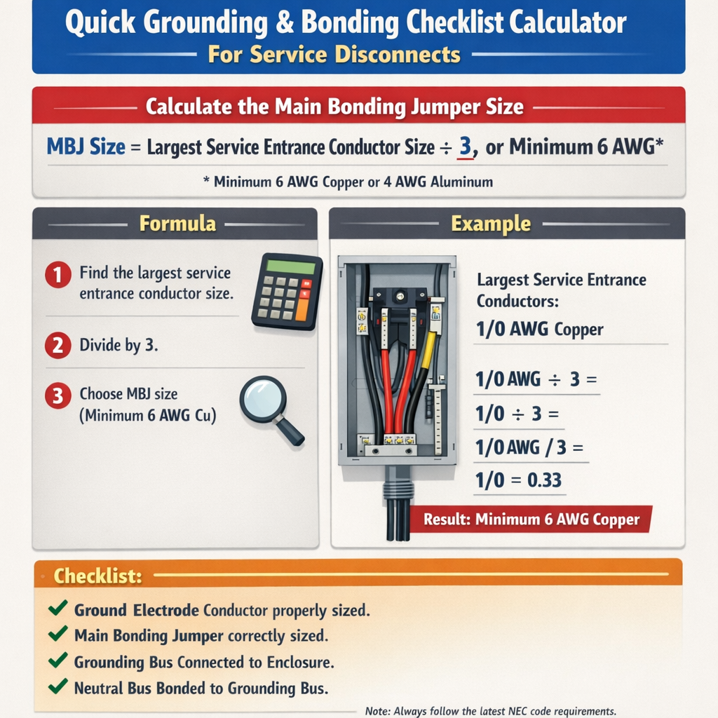
NEC 250.24 Quick Grounding and Bonding Checklist Calculator for Service Disconnects (Minimum GEC Sizing)
Scope and purpose of the quick grounding bonding checklist calculator
This document offers a practical, standards-based procedure and on-paper calculator method to size bonding conductors and verify grounding paths for service disconnects per NEC 250. It targets electrical engineers, field electricians, inspectors, and design professionals who need quick deterministic checks for service bonding jumpers and equipment grounding conductors.
Key NEC references and allied standards
- NFPA 70, National Electrical Code (NEC), Article 250 — Grounding and Bonding. See NFPA 70 (latest edition) for full text: https://www.nfpa.org
- NEC Table 250.122 — Minimum size of equipment grounding conductors (based on overcurrent protective device rating).
- NEC 250.66 — Grounding electrode conductor sizing rules for services and separately derived systems.
- NEC 250.28 — Bonding at service equipment and requirements for bonding jumper connections.
- IEEE 80 — Guide for Safety in AC Substation Grounding (for large systems prospective fault current and ground grid design): https://standards.ieee.org
- UL 467 — Standard for Grounding and Bonding Equipment (connectors and clamps): https://ul.com
Fundamental principles used by the quick calculator
The calculator uses direct-circuit resistance methods and prospective fault current to verify that the bonding path impedance is low enough to operate the overcurrent protective device (OCPD) within its time-current characteristic. It is a screening tool, not a replacement for full system short-circuit analysis or NEC compliance checks.
Basic fault loop resistance criterion
For a line-to-ground bolted fault, the bonding path resistance must be low enough so that the available fault current through the bonding path will cause the OCPD to clear quickly. The maximum allowed resistance of the bonding path (R_allow) is approximated by:
Where:
- V_system = nominal phase-to-neutral voltage that will be impressed across the fault (typical values: 120 V for single-phase service; 240 V between phases for multi-phase; use appropriate line-to-neutral where relevant).
- I_required = minimum fault current needed to trip the OCPD within acceptable clearing time (see device characteristic or use prospective fault current available at service).
Conductor DC resistance formula (used for quick sizing)
Use the conductor resistance relation to estimate bonding conductor resistance:
Where:
- R = resistance (ohms)
- ρ = resistivity (Ω·m) — typical values: copper 1.724 × 10⁻⁸ Ω·m at 20°C; aluminum 2.82 × 10⁻⁸ Ω·m at 20°C
- L = length of conductor (m) (one-way length from fault point to service bonding point — for roundtrip loop use 2 × L)
- A = cross-sectional area (m²) (for AWG use converted mm²)
For practical field calculations with AWG units and feet, use tabulated DC resistance per unit length (see tables below).
Practical parameter values and assumptions for the quick calculator
- Temperature correction: conductor resistance increases with temperature. Typical screening uses 20 °C resistances for conservative short-duration fault calculations; for sustained conditions, apply temperature correction factors.
- Contact resistance: include an allowance for lugs and connections (typically add 10–20% to conductor resistance to account for joints and terminations if high accuracy is required).
- Prospective fault current: obtain from utility short-circuit data or calculate from transformer rated impedance and source contributions.
- Acceptable clearing time: typically the OCPD trip curve determines acceptable I_required. A conservative practice is to ensure the initial prospective fault current exceeds the instantaneous/momentary pickup of the OCPD.
NEC quick sizing table: equipment grounding conductor (EGC) by OCPD — common values
| OCPD Rating (A) | Minimum EGC Copper (AWG) | Minimum EGC Aluminum (kcmil) |
|---|---|---|
| 15 | 14 | — |
| 20 | 12 | — |
| 30 | 10 | — |
| 60 | 10 | — |
| 100 | 8 | — |
| 200 | 6 | — |
| 400 | 3 | 2/0 |
| 600 | 2/0 | 3/0 |
| 800 | 3/0 | 350 kcmil |
| 1000 | 4/0 | 400 kcmil |
Note: The table is illustrative; always confirm with NEC Table 250.122 and the specific edition adopted in the jurisdiction. For certain conditions (e.g., parallel conductors, equipment-specific exceptions), use full NEC guidance.
Conductor DC resistance and cross-sectional area table (common AWG sizes)
| AWG | Area (mm²) | DC Resistance (Ω/1000 ft) @20°C |
|---|---|---|
| 14 | 2.08 | 2.525 |
| 12 | 3.31 | 1.588 |
| 10 | 5.26 | 0.999 |
| 8 | 8.37 | 0.6282 |
| 6 | 13.30 | 0.3951 |
| 4 | 21.15 | 0.2485 |
| 2 | 33.63 | 0.1563 |
| 1/0 | 53.48 | 0.0983 |
| 2/0 | 67.43 | 0.0779 |
| 3/0 | 85.01 | 0.0618 |
| 4/0 | 107.2 | 0.0490 |
Step-by-step quick checklist for service disconnect bonding verification
- Identify service type and disconnect location(s). Verify service conductors and grounding electrode conductor (GEC) routing per NEC 250.24 and 250.28.
- Obtain OCPD rating for the service disconnect(s) and transformer or utility data for prospective fault current.
- Select initial bonding conductor size per NEC Table 250.122 as baseline minimum.
- Calculate available prospective fault current at the service bonding point (I_pf). If unknown, request utility data or use transformer kVA and %Z to estimate.
- Compute R_allow = V_system / I_pf (use phase-to-neutral where the fault is line-to-ground).
- Compute actual bonding path resistance using tabulated resistances and connection allowances: R_path = R_conductor + R_terminations + R_other conductors
- If R_path ≤ R_allow, bonding conductor is acceptable. If not, increase conductor size or shorten length and re-evaluate.
- Document bonding jumper routing, clamp type (UL-listed), torque values, and continuity verification procedures.
Calculator formulas and variable explanations with typical values
Use the following equations for the quick calculator. All variables are defined and typical values shown for common conditions.
Equation 1 — Allowable bonding path resistance
- R_allow (Ω) — maximum allowable resistance of the bonding path to achieve required fault current.
- V_system (V) — nominal phase-to-neutral voltage for single-phase systems (typical 120 V) or appropriate impressed voltage for other configurations.
- I_pf (A) — prospective fault current at the fault location (A). Typical service values: residential small services 500–10,000 A depending on utility; commercial services often 10 kA–50 kA or more.
Equation 2 — Conductor resistance (roundtrip)
- R_conductor (Ω) — DC resistance of the bonding conductor included in the fault loop.
- R_per_length (Ω/ft or Ω/m) — tabulated resistance per unit length for the conductor size (see table).
- L_roundtrip (ft or m) — total conductor distance traversed by the fault current (usually two times the one-way length from fault to bonding point).
Equation 3 — Required conductor area by rearranging resistance formula
- A_required (m²) — required cross-sectional area to achieve R_conductor ≤ R_allow given conductor length and material resistivity.
- ρ (Ω·m) — resistivity of conductor material (typical copper = 1.724×10⁻⁸ Ω·m, aluminum = 2.82×10⁻⁸ Ω·m).
- Note: convert A_required to standard AWG or kcmil using area conversion tables.
Real case example 1 — Residential service bonding jumper sizing
Scenario:
- Single-family dwelling with 120/240 V single-phase service, main service OCPD = 200 A.
- Distance from service equipment bonding point to main panel metal service mast spliced point = 20 ft one-way (bonding jumper one-way length = 20 ft).
- Utility reports available prospective line-to-ground fault current = 10,000 A at the service point.
- Use copper bonding jumper.
Step 1 — Determine NEC baseline:
NEC Table 250.122 lists minimum EGC for 200 A OCPD as AWG 6 copper. This is the baseline minimum.
Step 2 — Compute allowable bonding path resistance:
Step 3 — Compute conductor resistance (roundtrip length = 2 × 20 ft = 40 ft).
Use AWG 6 copper resistance from table: 0.3951 Ω/1000 ft.
Step 4 — Add connection allowance (assume +15% for terminals):
Step 5 — Compare R_total to R_allow:
R_total (0.01817 Ω) > R_allow (0.012 Ω) — not acceptable for quick fault clearing expectation.
Step 6 — Increase conductor size to AWG 4 copper and recalc:
R_total (0.01143 Ω) ≤ R_allow (0.012 Ω) — acceptable.
Result and action:
- Although NEC Table 250.122 permitted AWG 6, the available prospective fault current and length require AWG 4 copper bonding jumper to ensure sufficient fault current to operate the OCPD rapidly.
- Document the deviation from Table 250.122 with calculations, specify copper AWG 4 bonding jumper, use UL-listed connectors, and tighten to manufacturer torque values.
Real case example 2 — Small commercial service with aluminum bonding conductor option
Scenario:
- Commercial building 480 V 3-phase wye service; line-to-neutral voltage = 277 V. Main OCPD = 400 A.
- One-way bonding distance from service equipment to remote exposed metalwork = 60 ft (roundtrip = 120 ft).
- Utility provides prospective line-to-ground fault current = 20,000 A at service.
- Plan to use aluminum conductor for bonding jumper due to weight and cost constraints.
Step 1 — Baseline per NEC Table 250.122 for 400 A OCPD indicates minimum EGC copper = AWG 3, or aluminum size approximate 2/0 (confirm table specifics). For this exercise assume aluminum 2/0 is baseline.
Step 2 — Compute allowable bonding path resistance (use the line-to-neutral voltage that will be impressed on a ground fault — 277 V):
Step 3 — Compute conductor resistance for aluminum 2/0. Use aluminum resistivity as approximate via resistance per 1000 ft. Typical 2/0 Al DC resistance ≈ 0.0779 Ω/1000 ft for copper 2/0; for aluminum 2/0 the value is higher. For conservative calculation, use 0.2 Ω/1000 ft (conservative approximate). Better to use manufacturer data; here we use 0.2 Ω/1000 ft.
Step 4 — Add 15% termination allowance:
Step 5 — Compare to R_allow:
R_total (0.0276 Ω) > R_allow (0.01385 Ω) — unacceptable.
Step 6 — Increase aluminum size to 350 kcmil (typical larger size), and use manufacturer resistance ~0.049 Ω/1000 ft (approx for large aluminum). R_conductor = 0.049 × 0.12 = 0.00588 Ω
R_total (0.00676 Ω) ≤ R_allow (0.01385 Ω) — acceptable.
Result and action:
- Aluminum 2/0 is inadequate for the required loop impedance given the 60 ft one-way distance and available fault current. Use aluminum 350 kcmil or switch to copper (smaller size) to meet the R_allow criterion.
- Verify connector ratings, thermal expansion allowances for aluminum-to-steel terminations, and use antioxidant compounds and proper torque values per UL 467 and equipment manufacturer guidance.
Additional practical considerations and verification steps
- Bonding path continuity: measure loop resistance with a clamp-on microhmmeter where possible. Compare measured values to calculated R_total to detect excessive joint resistance or damaged conductors.
- Use proper listed bonding clamps and permanent electro-mechanical connections; avoid relying solely on paint or structural contacts without verified listed bonding hardware.
- Where parallel conductors are used, ensure equal length and proper paralleling practice per NEC to share fault current.
- Large installations require full short-circuit analysis (per IEEE/ANSI methods) and protective device coordination studies, not just the quick calculator screening.
- GEC sizing (NEC 250.66) differs from EGC sizing; ensure GEC (to electrode) follows the correct rule set and is routed appropriately without splices except at permitted points.
- When bonding metal underground systems (pipes, structural steel), verify corrosion protection and bonding clamping that meet UL and NEC requirements.
Common field checklist items for installation and inspection
- Confirm bonding conductor material (copper vs. aluminum) and type (insulated vs. bare) per application and equipment requirements.
- Verify conductor size per NEC or calculated requirement; mark larger-than-NEC sizes in drawings and field documentation.
- Ensure bonding jumpers are as short and direct as practical to minimize loop impedance.
- Use listed connectors and clamps; verify size range and torque specifications.
- Inspect terminations for cleanliness, remove paint/galvanizing where required to obtain low resistance, and recoat where necessary to prevent corrosion.
- Document measurement of loop impedance or micro-ohm readings and include date, person, instrument used (make/model), and measurement method.
- Provide labelling on service equipment showing bonding conductor size and route for future maintenance.
References and further reading
- NFPA 70 (NEC) — Article 250, Grounding and Bonding. Purchase or view code extracts at NFPA: https://www.nfpa.org/NEC
- NEC Table 250.122 — Equipment grounding conductor sizing table (consult the current adopted edition of NEC).
- NEC 250.66 — Grounding electrode conductor sizing rules and exceptions.
- IEEE Std 80 — Guide for Safety in AC Substation Grounding. Useful for advanced grounding grid calculations: https://standards.ieee.org/standard/80-2013.html
- UL 467 — Grounding and Bonding Equipment standard — connectors, clamps, and bonding accessories: https://ul.com
- Manufacturer datasheets for conductor resistance and connector torque values (e.g., Southwire, AAAC, or equivalent).
Best practices summary for rapid field decisions
- Start with NEC Table minimums, but always confirm by calculation when distances are long or available fault current is low.
- Use the R_allow = V / I_pf method to screen conductor sizes; include termination and joint allowances.
- Prefer copper where conductor length or exposure to corrosion is uncertain; aluminum requires careful terminations and typically larger sizes.
- Perform a physical continuity test and micro-ohm measurement after installation; measure and record loop impedance when possible.
- For critical facilities, follow up with a full short-circuit and coordination study and consult the utility for exact available fault current data.
Quick-reference equations (for printing)
Regulatory note and disclaimer
This article provides technical guidance for quick screening assessments and does not replace the NEC text, local amendments, or full engineering studies required for code compliance. Always consult the applicable NEC edition adopted by the authority having jurisdiction, and engage a licensed electrical engineer for designs requiring full fault current analysis, equipment coordination, or deviations from prescriptive code tables.