This article describes a free motor overload setting calculator based on nameplate current methodology principles.
It details calculations, normative references, sample cases, and implementation guidelines for accurate protective settings review.
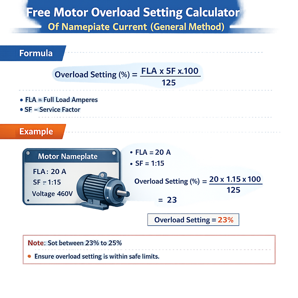
Motor Overload Setting Calculator: % of Nameplate Current (General Method)
Scope and Purpose
This document defines a general method for calculating thermal overload relay settings using motor nameplate current.
It targets electrical engineers, protection technicians, and system integrators verifying overload protection selections.
Fundamental Principles of Nameplate-Based Overload Settings
Motor overload protection must allow normal starting and transient loading while preventing sustained overheating that causes insulation damage and bearing failures. Nameplate full-load current (FLC) is the baseline parameter used by protection devices to set trip thresholds because it represents rated steady-state current at rated voltage and frequency.
Overload relays (thermal, electronic or thermal-magnetic devices) are adjusted relative to the motor FLC, often modified by service factor, ambient temperature, mounting considerations and applicable standards. The following sections present the general calculation method and explanatory formulas.
General Calculation Method — Step by Step
- Gather motor nameplate data: rated power (kW or hp), rated voltage, rated frequency, full-load current (if provided), service factor (SF), power factor (PF), and efficiency (η).
- If FLC is not provided on the nameplate, calculate it from rated power using three-phase or single-phase equations.
- Adjust FLC for service factor, ambient temperature and mounting to derive the allowable continuous current the motor can sustain without overheating.
- Select an overload relay with an adjustable range that encompasses the adjusted current. Choose trip class/time and calibration features suited to starting and duty cycle.
- Document setting, expected trip current and trip time curves; verify with manufacturer curves and applicable normative limits before commissioning.
Required Input Parameters
- Rated power: P (kW) or hp
- Rated voltage: V (line-to-line for three-phase)
- Frequency: f (Hz)
- Nameplate full-load current: I_nameplate (A) — if available
- Service factor: SF (unitless)
- Power factor: PF (typical 0.8–0.9 for induction motors at load)
- Efficiency: η (0–1)
- Ambient temperature and enclosure/mounting (for correction factors)
- Desired safety margin or normative maximum setting
Formulas and Variable Definitions
Use the following HTML-presented formulas. Variables are explained with typical values for induction motors.
Three-phase motor full-load current (A):
Where:
- P_kW = rated motor output in kilowatts. Typical values: 0.75 kW, 1.5 kW, 7.5 kW, 15 kW.
- V_line = line-to-line voltage (V). Common: 230 V, 400 V, 480 V, 600 V.
- PF = power factor (unitless). Typical loaded induction motor: 0.75–0.95.
- η = efficiency (unitless). Typical range: 0.80–0.95 depending on motor size and design.
- √3 = 1.73205080757 (constant for three-phase relationship).
Single-phase motor full-load current (A):
Conversion from horsepower to kilowatts:
Adjusted allowable continuous current considering service factor and ambient/mounting corrections:
Where:
- SF = service factor (typical values: 1.0, 1.15, 1.25). If nameplate shows SF, use it; otherwise assume SF = 1.0 unless motor rated otherwise.
- K_ambient = ambient temperature correction factor (manufacturer-specific; typical examples provided later).
- K_mount = mounting or enclosure correction factor (if relay or motor is enclosed in restricted ventilation).
Recommended overload relay setting (A):
Typical safety margin: 0.95–1.05 depending on standard and application. For many control panels a margin of 0.95–1.10 is applied to balance nuisance trips versus protection.
Tables of Common Values and Ranges
| Motor Power | Typical Efficiency η | Typical Power Factor PF | Approx. FLC at 400 V (A) | Approx. FLC at 480 V (A) |
|---|---|---|---|---|
| 0.75 kW (1 hp) | 0.75 | 0.80 | 1.4 | 1.2 |
| 1.5 kW (2 hp) | 0.78 | 0.82 | 2.7 | 2.3 |
| 3.0 kW (4 hp) | 0.85 | 0.85 | 5.0 | 4.2 |
| 7.5 kW (10 hp) | 0.88 | 0.88 | 12.0 | 10.0 |
| 15 kW (20 hp) | 0.90 | 0.90 | 24.0 | 20.0 |
| 30 kW (40 hp) | 0.92 | 0.92 | 47.0 | 39.0 |
| 75 kW (100 hp) | 0.94 | 0.94 | 113.0 | 93.0 |
| Service Factor (SF) | Interpretation | Typical Allowed Overload |
|---|---|---|
| 1.00 | No continuous overload allowed above nameplate | 100% of FLC |
| 1.10 | 10% additional continuous load allowed | 110% of FLC |
| 1.15 | 15% additional continuous load allowed | 115% of FLC |
| 1.25 | 25% additional continuous load allowed (heavy-duty motors) | 125% of FLC |
| Ambient Temperature (°C) | Typical K_ambient (example) | Notes |
|---|---|---|
| ≤ 25°C | 1.05 | Relays slightly overrange; better cooling |
| 25–35°C | 1.00 | Reference condition for most relays |
| 35–45°C | 0.95 | Derate to avoid nuisance trip at higher ambient |
| >45°C | 0.90 | Significant derating; consult manufacturer |
| Overload Relay Range Example (Manufacturer Typical) | Adjustment Range (A) | Suitable for Motors (A) |
|---|---|---|
| Range 1 | 0.1 – 0.16 A | Small fractional hp motors |
| Range 2 | 0.55 – 0.85 A | 1–3 hp motors |
| Range 3 | 5 – 8 A | 7.5–10 kW range |
| Range 4 | 20 – 32 A | 30–75 kW range |
| Range 5 | 85 – 150 A | Large motors and motor starters |
Selecting Overload Relay Setting: Practical Equation
Most typical installations follow the simplified selection equation:
Where K_margin is a chosen margin factor to avoid nuisance tripping during short transients (typical range 0.95–1.10). Always confirm that the final Setting_A does not exceed the maximum permitted by the applicable standard or nameplate restrictions.
Real Example 1 — Three-Phase Motor, Compute FLC and Set Relay
Data (nameplate partially provided): Motor rated 15 kW, 400 V, PF estimated 0.90, efficiency 0.92, service factor 1.15, ambient 40°C, panel with moderate ventilation.
Step 1 — Compute nameplate full-load current (if not present)
Use the three-phase formula:
Insert values:
Compute denominator: 1.732 × 400 × 0.90 × 0.92 = 1.732 × 400 × 0.828 = 1.732 × 331.2 = 573.57
Step 2 — Apply service factor and correction factors
Step 3 — Choose margin and final setting
Step 4 — Select overload relay range and trip class
Choose a relay whose adjustable range includes 28.0 A. From the example table, Range 4 (20–32 A) is suitable. Select trip class based on starting method: use Class 10 for moderate inrush, Class 20 for heavy-load starting; verify manufacturer trip curves.
Verification
- Confirm Setting_A (28.0 A) ≤ relay maximum continuous rating and relay selected covers 28.0 A in its adjustment span.
- Check that relay trip time at 150% of Setting_A matches application tolerance (consult manufacturer).
- Document setting and apply nameplate and standard constraints.
Real Example 2 — Motor with Nameplate FLC Given and Tight Ambient
Data: Motor nameplate FLC = 50 A at 480 V, SF = 1.0, ambient expected 50°C (rooftop), ventilation restricted (K_mount = 0.95).
Step 1 — Apply ambient and mounting corrections
From the ambient correction table, at 50°C K_ambient typical = 0.90 (see caution: manufacturer-specific).
Step 2 — Safety margin and final setting
Step 3 — Relay selection
Select an overload relay with an adjustable range that covers 42.0 A. If relay ranges are 35–50 A, select that range and adjust dial to 42.0 A.
Step 4 — Additional checks
- Verify starting current (inrush) and ensure trip class accommodates inrush without nuisance trips.
- Consider electronic overloads with PTC/thermal compensation when ambient varies widely.
- Document the reasons for derating in the maintenance records.
Considerations for Starting Methods and Trip Class
Overload relays must be matched not only by current but also by time‑delay/trip characteristics. Key considerations:
- Direct-on-line (DOL) starting: moderate inrush but short duration. Typical trip class: 10A or 20 depending on motor size.
- Star-delta, soft-starters, or VFD: reduced starting currents — electronic overloads with motor thermal models are recommended.
- Frequent starting or cyclic duty: consult motor thermal limits and consider motors with higher SF or design for intermittent duty.
- Ambient extremes and enclosure class (IP rating) affect heat dissipation; use correction factors or use relay with ambient compensation.
Practical Implementation, Testing and Commissioning
- Set relay according to computed Setting_A and lock or document setting.
- Measure actual motor no-load current and full-load current under test conditions when feasible.
- Compare manufacturer thermal trip curves at the selected setting; plot expected trip times at various multiples of Setting_A.
- Conduct trial starts and monitored runs to verify no nuisance trips occur and that the motor remains within temperature limits.
- Record final settings, manufacturer relay type/range, trip class and measured motor currents in commissioning report.
Measurement and Validation Techniques
- Use true-RMS clamp meters to measure starting and steady-state currents.
- Use thermography or temperature sensors on motor casing to validate cooling performance under load.
- When possible perform locked-rotor and locked-stator tests only when safe and authorized; prefer manufacturer test protocols.
- Validate relay calibration periodically per maintenance schedule and after any motor overhaul.
Normative References and Authoritative Sources
Consult the relevant standards and manufacturer documents for binding requirements and calibrated correction factors. Typical normative references include:
- NFPA 70 (NEC), Article 430 — Motors, Motor Circuits, and Controllers: https://www.nfpa.org/NEC
- IEC 60947 series — Low-voltage switchgear, contactors and motor-starters: https://www.iec.ch/standards
- NEMA MG 1 — Motors and Generators (constructors and ratings): https://www.nema.org
- IEEE and C37 series for protection practice and device coordination: https://standards.ieee.org
- Manufacturer application guides (Siemens, ABB, Schneider Electric, Eaton) — for relay-specific correction/selection charts
Note: Specific derating coefficients and allowable maximum settings depend on the protective device manufacturer and applicable national/local code. Always cross-check the selected Setting_A against the device's published calibration and the requirements of the controlling standard.
Best Practices and Common Pitfalls
- Do not set overload protection above the motor nameplate FLC times allowable SF when the nameplate prohibits it.
- Always use accurate PF and η for computed FLC; conservative assumptions can prevent underprotection but may increase nuisance trips.
- Account for ambient and enclosure derating before finalizing settings; ignoring these leads to premature tripping or motor heating.
- Be cautious when using non-thermal electronic overload relays; ensure they emulate motor thermal behavior or use motor thermal models provided by manufacturer.
- Document all assumptions, correction factors and the justification for chosen K_margin values for future maintenance.
Appendix: Quick Reference Calculation Examples
| Parameter | Formula / Value | Notes |
|---|---|---|
| Three-phase FLC | I_fl = (P_kW × 1000) / (√3 × V × PF × η) | Use measured PF and η for precision |
| Single-phase FLC | I_fl = (P_kW × 1000) / (V × PF × η) | Apply when motor is single-phase |
| Derated allowable current | I_allowable = I_fl × SF × K_ambient × K_mount | Product of nameplate baseline and correction factors |
| Final relay setting | Setting_A = I_allowable × K_margin | K_margin often 0.95–1.05 per application |
Further Reading and Tools
- Manufacturer calculators and selection tools — ABB Motor Selection, Siemens Motor Starter Guides, Schneider Electric motor starter documentation.
- IEC and NEMA standard documents for prescriptive requirements affecting overload settings and branch-circuit protection.
- Technical papers and IEEE articles on motor thermal models and electronic overload protection strategies.
Final Notes on Safety and Compliance
Setting motor overload devices is an engineering activity that balances protection and operational reliability. The general method presented here is intended as a technical guide; final settings must comply with local codes, motor nameplates, product manuals and employer safety procedures. When in doubt, consult motor and relay manufacturers or a qualified protection engineer for site-specific verification and commissioning.
References
- National Fire Protection Association, NFPA 70 — National Electrical Code (NEC). https://www.nfpa.org/NEC
- International Electrotechnical Commission (IEC) standards library. https://www.iec.ch
- NEMA — Standards and publications, including NEMA MG 1. https://www.nema.org
- IEEE Standards Association — motor protection and coordination standards. https://standards.ieee.org
- Representative manufacturers: ABB (https://new.abb.com), Siemens (https://new.siemens.com), Schneider Electric (https://www.se.com)