Accurate copper cable sizing ensures safety, efficiency, and compliance across electrical installations worldwide and reliability.
This article details a must-have affordable copper cable calculator, features, formulas, tables, and examples practical.Copper Conductor Size & Voltage Drop Calculator — Affordable Practical Options
Why a must-have affordable copper cable calculator matters
An effective copper cable calculator integrates regulatory limits, thermal behavior, and economical choices.
Engineers and technicians reduce risk, save material costs, and meet performance targets using such a tool.
Key parameters and constraints for copper cable selection
Fundamental electrical parameters
- Current (I): steady-state continuous current the conductor must carry (A).
- Voltage level (V): system nominal voltage for voltage drop calculations (V).
- Power factor (pf): important for AC systems when using impedance components.
- Length (L): one-way physical run between source and load (m).
- Allowable voltage drop (% or V): design constraint often 3%–5% for lighting and general use.
- Ambient temperature and grouping: affect ampacity via correction factors.
- Short-circuit withstand energy (I²t) and protection device characteristics.
Material and conductor properties
The following physical relations are essential and form the calculator's computational core.
- R = conductor resistance (Ω)
- ρ = copper resistivity ≈ 1.724e-8 Ω·m at 20°C
- L_total = round-trip length for DC or single-phase circuits (m)
- A = cross-sectional area (m²); for standard sizes use mm² converted to m² (A_mm2 × 1e-6)
For cable calculators use the per-kilometre resistance tables standardized in IEC 60228: R_20 (Ω/km) values.
- Vd = voltage drop (V)
- I = load current (A)
- R_20 = conductor resistance at 20°C (Ω/km)
- L_km = one-way length in kilometres (km); for round trip multiply by 2 when R_20 is one-way resistance
- R and X are per-phase series resistance and reactance per km
- cosφ and sinφ are power factor components
Essential formulas implemented in the calculator (HTML only)
- ρ (copper, 20°C) = 1.724e-8 Ω·m
- L = length in metres
- A = conductor cross-sectional area in m² (mm² × 1e-6)
Temperature correction for resistance at operating temperature T°C:
- R_T = resistance at temperature T (Ω)
- R_20 = resistance at 20°C (Ω)
- α = temperature coefficient for copper ≈ 0.00393 /°C
- T = conductor operating temperature (°C)
- R_20 in Ω/km and L_km one-way length in km. Multiply by 2 for return path.
- R_total includes temperature-corrected resistance for the circuit length (Ω)
Standard conductor resistance and typical ampacity table
| Conductor (mm²) | DC Resistance R_20 (Ω/km) | Typical Ampacity (A) at 30°C (single-core, protected) | Approx. Reactance X (Ω/km) |
|---|---|---|---|
| 1.0 | 18.10 | 15–20 | 0.08 |
| 1.5 | 12.10 | 18–24 | 0.07 |
| 2.5 | 7.41 | 24–32 | 0.06 |
| 4 | 4.61 | 32–45 | 0.05 |
| 6 | 3.08 | 41–60 | 0.045 |
| 10 | 1.83 | 57–90 | 0.04 |
| 16 | 1.15 | 76–120 | 0.035 |
| 25 | 0.727 | 101–170 | 0.032 |
| 35 | 0.524 | 125–200 | 0.030 |
| 50 | 0.387 | 150–240 | 0.028 |
| 70 | 0.268 | 200–320 | 0.025 |
| 95 | 0.193 | 230–400 | 0.023 |
| 120 | 0.153 | 260–470 | 0.021 |
| 150 | 0.124 | 300–550 | 0.020 |
| 185 | 0.100 | 340–640 | 0.018 |
| 240 | 0.077 | 420–800 | 0.016 |
Notes: R_20 values follow IEC 60228 typical figures. Ampacity depends heavily on installation method, insulation type, ambient temperature, and grouping. Reactance X values shown are approximations for compact conductors and vary by geometry.
Correction factors, grouping, and temperature influences
| Condition | Typical Correction Factor (k) | Comment |
|---|---|---|
| Ambient 30°C reference | 1.00 | Base ampacity tables use this condition |
| Ambient 40°C | 0.91 | Reduce allowable current |
| Ambient 50°C | 0.82 | Further reduction |
| More than 3 cores in conduit | 0.70–0.90 | Depends on number of cores and spacing |
| Buried directly in ground | 0.95–1.00 | Soil thermal resistivity critical |
| Conductor insulation type (XLPE vs PVC) | XLPE usually higher temp rating | XLPE supports higher continuous temp |
Calculator must allow input of ambient temperature, number of loaded cores, soil thermal resistivity, and insulation type. Apply correction factors multiplicatively to the base ampacity.
How an affordable calculator implements multi-constraint selection
A robust yet low-cost copper cable calculator evaluates multiple constraints and returns the minimum compliant cross-section.
- Compute required continuous current margin (I_req = load current × safety factor).
- Apply grouping and temperature correction factors to candidate cable ampacities.
- Check thermal short-circuit withstand if required.
- Calculate voltage drop for each candidate and ensure it stays under allowable percent.
- Select smallest cross-section meeting ampacity and voltage drop and considering economic trade-offs.
Objective function for affordability
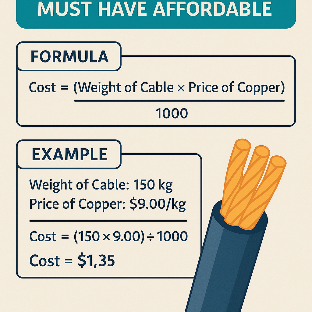
Cost-based selection can use an objective function combining conductor cost and power loss cost over life:
- Capital_cost(A) = unit_cost_per_meter(A) × length
- Energy_cost_loss(A) = P_loss(A) × operating_hours_per_year × energy_price × years
Example 1 — Single-phase lighting circuit: step-by-step solution
Problem statement: Design a single-phase 230 V lighting circuit supplying 18 kW of resistive loads distributed along a 40 m run. Maximum allowable voltage drop 3% (6.9 V). Ambient 30°C. Choose economical copper conductor.
Step 1 — Determine continuous current
Step 2 — Choose candidate sizes by ampacity
From table: 10 mm² ampacity approx 68–90 A (borderline), 16 mm² approx 76–120 A.
Because continuous current > 75 A and safety margin recommended, start with 16 mm² candidate.
Step 3 — Voltage drop check for 16 mm²
Round-trip factor for single-phase: 2
Vd = 2 × I × R_20 × L_km = 2 × 78.26 × 1.15 × 0.04 = 7.20 V
Result: Slightly above 3% allowable. 16 mm² fails voltage drop requirement.
Step 4 — Try 25 mm²
Vd% = (4.56 / 230) × 100% = 1.98% — acceptable.
Step 5 — Final check ampacity and affordability
25 mm² ampacity ~101–170 A, sufficient. Compare life-cycle cost: 25 mm² material cost higher but reduced losses. For lighting loads dominated by energy use, a short payback period may justify up-sizing; however for affordability and regulation, 25 mm² is selected to meet voltage drop and ampacity.
Example 2 — Three-phase motor feeder with power factor: full development and solution
Problem statement: Select a copper feeder from a 400 V three-phase supply to a 150 kW motor, pf = 0.9 lagging, cable length one-way 120 m. Maximum voltage drop 3% (400 V × 3% = 12 V). Ambient 35°C; use XLPE-insulated multi-core in conduit. Start with minimum compliant conductor size while minimizing life-cycle cost.
Step 1 — Determine line current
Step 2 — Candidate sizes by ampacity (base values at 30°C)
- 50 mm² ampacity ~165 A — insufficient
- 70 mm² ~200–320 A — may suffice with correction
- 95 mm² ~230–400 A — better candidate
- 120 mm² ~260–470 A — higher capacity
Apply ambient correction: ambient 35°C (k_temp ≈ 0.96). Grouping factor for multi-core in conduit (assume small grouping, k_group ≈ 0.9). Effective correction k_total ≈ 0.86. So required base ampacity = I_line / k_total = 240.6 / 0.86 = 279.8 A.
Thus 95 mm² base ampacity (≈ 230–400 A) might be borderline depending on selected base number; 120 mm² (260–470 A) comfortably covers corrected required ampacity. Prefer 120 mm² for margin.
Step 3 — Voltage drop check for 95 mm² and 120 mm²
For 95 mm², R_20 = 0.193 Ω/km. L_km = 0.12 km. Vd_95 = 1.732 × 240.6 × 0.193 × 0.12 = 9.62 V → 2.41% (<3%), acceptable.
For 120 mm², R_20 = 0.153 Ω/km. Vd_120 = 1.732 × 240.6 × 0.153 × 0.12 = 7.63 V → 1.91% — also acceptable.
Step 4 — Reconcile ampacity vs voltage drop
Although 95 mm² meets voltage drop, its corrected ampacity may be insufficient if base table lower bound < 280 A. Therefore 120 mm² is selected to satisfy corrected ampacity and provide margin. Evaluate short-circuit and protective device ratings separately; ensure conductor adiabatic equation compliance for fault clearing time.
Step 5 — Adiabatic short-circuit check (simplified)
Adiabatic equation: S_required = I_sc × √t ≤ k × S × 10³ (where S is conductor cross-section mm² and k is material constant)
Rearranged to check if chosen S withstands prospective fault current I_sc for protection clearing time t. The calculator must compute and verify this condition using appropriate k values from standards (k for annealed copper depends on maximum temperature).
Short-circuit withstand and protective device coordination
Designers must verify that the chosen conductor can withstand thermal and mechanical stresses during short-circuit events. The adiabatic equation is:
- S_min = minimum cross-sectional area in mm²
- I_short = prospective fault current in kA
- t = protection device clearing time in seconds
- k = material constant (for copper, typical k values depend on final temperature; e.g., k ≈ 115 for 160°C, see standards)
Calculator input should support fault current estimation or accept a measured / calculated value from system studies.
UX and feature set for an affordable but professional calculator
A practical affordable copper cable calculator intended for international use should include:
- Multi-unit input/output (A, kW, mm², AWG)
- Pre-populated tables for R_20, X, and ampacity per IEC/NEC/BS standards
- Configurable ambient temperature, grouping factors, and insulation types
- Voltage drop limits and automatic checks
- Short-circuit adiabatic checks with input for available fault current and protective device clearing times
- Life-cycle cost estimation module
- Exportable report that shows assumptions, normative references, and step-by-step calculations
Validation against standards and recommended references
Calculator must cite and implement normative corrections following recognized standards. Reference key documents:
- IEC 60364 — Electrical installations of buildings (design and selection rules): https://www.iec.ch
- IEC 60228 — Conductors of insulated cables: https://www.iec.ch
- NEC (NFPA 70) — National Electrical Code (USA) ampacity and installation rules: https://www.nfpa.org
- BS 7671 — Requirements for Electrical Installations (IET Wiring Regulations): https://www.theiet.org/
- IEEE standards for cable ampacity and short-circuit ratings: https://standards.ieee.org
Authoritative online resources for tables and formulas include manufacturer datasheets (e.g., Prysmian, Nexans) and standards organizations specified above. When implementing an affordable tool, license required standards where necessary or use published permissive data.
Accuracy considerations and limitations
- Skin effect and proximity effect: at low-voltage power frequencies (50/60 Hz) and common conductor sizes, DC resistance approximation is usually adequate for voltage drop; for harmonics or high frequencies, use complex impedance models.
- Reactance contributions: for three-phase circuits, include line reactance X. For long runs or high-power installations, X can meaningfully affect voltage drop.
- Soil thermal resistivity: for buried cables, soil resistivity heavily influences ampacity — the calculator should allow input of soil resistivity and burial depth.
- Harmonic currents: if significant harmonic content exists, derating of ampacity and increased losses may be required.
Implementation tips for an efficient affordable calculator
- Store standard tables for R_20 and X for common conductor sizes and geometries.
- Provide adjustable correction factor presets for quick regional defaults (IEC region, NEC region, BS region).
- Allow users to select calculation strictness: “regulatory only”, “practical design”, or “life-cycle optimized”.
- Pre-validate inputs and present warnings for common pitfalls (e.g., undervaluing voltage drop, ignoring grouping).
- Offer exportable calculation logs for compliance documentation with links to the specific normative clause used.
Security, multilingual capability, and SEO considerations
For broad adoption, the calculator must support multiple languages and units, be mobile-responsive, and secure when hosted online. SEO optimization for product pages and documentation should use focused keywords:
- Copper cable calculator
- copper cable sizing
- voltage drop calculator
- ampacity table copper
- affordable cable sizing tool
Provide schema-friendly output (structured data) and accessible exportable reports so search engines and professionals can find and evaluate the tool quickly.
Additional practical tables: allowable voltage drop and use cases
| Application | Typical Allowable Voltage Drop | Note |
|---|---|---|
| Lighting and general-purpose circuits | 2–3% | Protects lamp life and control gear |
| Motor feeders and heavy machinery | 3–5% | Consider inrush and motor starting torque |
| Control circuits and instrumentation | 1–2% | Sensitive to supply variation; often tighter limits |
| Emergency systems | 1–3% | Often specified by code or owner requirements |
| DC systems (battery banks) | 2–5% | Consider regulator and battery lifespan effects |
Checklist for engineers using an affordable calculator
- Confirm load types (resistive, inductive, motor) and duty cycles.
- Specify maximum permissible voltage drop and regulatory limits.
- Enter accurate run lengths and installation environment details.
- Include temperature, grouping, and soil data for ampacity correction.
- Validate short-circuit currents and protection clearing times for adiabatic checks.
- Review life-cycle cost output and compare with practical requirements.
- Document assumptions and normative references in reports for compliance records.
Final technical recommendations for calculator outputs
A professional affordable copper cable calculator should produce an output report that includes:
- Selected conductor size and insulation type
- Calculated voltage drop (V and %), power loss, and cable temperature-corrected resistance
- Ampacity checks with applied correction factors and final margin
- Short-circuit withstand validation with used k constants and fault current data
- Economic summary: capital cost vs energy-loss cost over expected life
- References to the standards and tables used (clause numbers if applicable)
Authoritative references and further reading
- IEC 60364 — International Electrotechnical Commission: https://www.iec.ch/
- IEC 60228 — Conductors of insulated cables: https://www.iec.ch/
- NFPA 70 (NEC): National Fire Protection Association: https://www.nfpa.org/
- IET Wiring Regulations (BS 7671): Institution of Engineering and Technology: https://www.theiet.org/
- NEMA and IEEE cable guides for ampacity and short-circuit calculations: https://standards.ieee.org/
- Manufacturer cable datasheets (examples: Prysmian, Nexans) for X and R values and installation recommendations.
Implementing the above ensures any affordable copper cable calculator delivers technically reliable and code-compliant recommendations. Use the provided tables, formulas, and worked examples as validation checks when building or evaluating tools.