Estimating neutral current quickly is essential for safe four-wire generator operation under unbalanced load conditions.
This technical guide provides formulas, examples, and estimators for fast, accurate neutral current calculation methods.
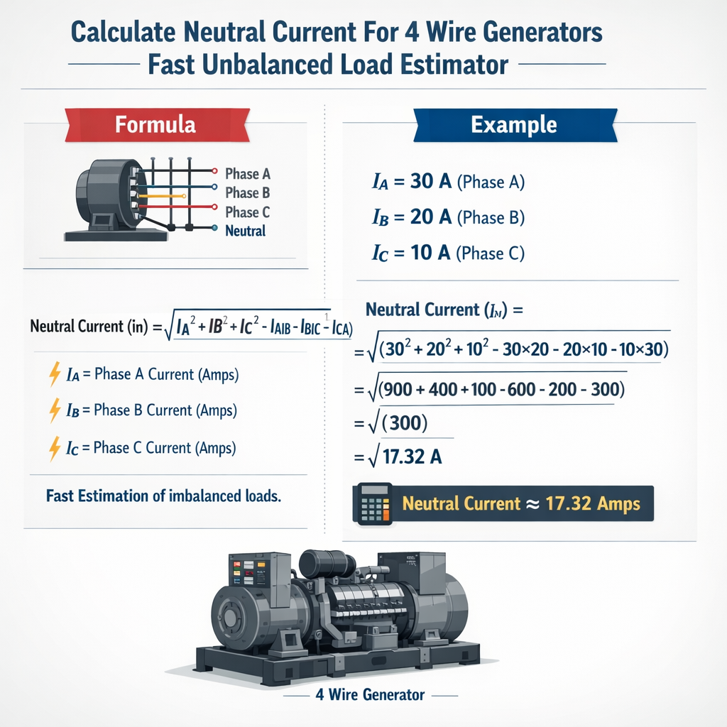
Neutral Current Estimator — 4‑Wire Generator (Fast Unbalanced Load)
Fundamentals of Neutral Current in Four-Wire Generators
A four-wire generator supplies three-phase loads with a neutral conductor returning the algebraic sum of phase currents. In sinusoidal steady-state phasor notation the neutral current I_n is the phasor sum of the three phase currents: the neutral conductor must carry I_n = I_a + I_b + I_c (phasors). For many engineering tasks it is essential to know the magnitude |I_n| and phase to size the neutral conductor, select protection and assess heating. Key physical phenomena that increase neutral current beyond simple resistive imbalance include:- Unequal single-phase loads across phases (amplitude imbalance).
- Phase-angle shifts between currents (power factor differences, reactive loads).
- Triplen harmonic currents (3rd, 9th, . . .) that add in neutral rather than canceling.
- Grounding scheme and neutral impedance at the generator (solid, resistor, reactance).
Core Mathematical Relations and Estimator Formulas
Phasor sum (exact steady-state expression)
The neutral phasor current is
Expanded in Cartesian components:
Explanation of variables and typical values:
- |I_x| — RMS magnitude of phase current (A). Typical ranges: 10 A to 1000 A depending on generator size.
- θ_x — phase angle of each phase current relative to phase A (degrees or radians). For balanced, θ_b = −120° and θ_c = +120°.
- I_n — neutral conductor phasor (A). Typically 0 A for perfectly balanced sinusoidal loads; can exceed largest phase current for extreme imbalance or harmonic conditions.
Symmetrical components and zero-sequence shortcut
Symmetrical components provide compact relations for neutral current:
Thus computing the zero-sequence component I_0 (the average of the three phase phasors) immediately yields the neutral phasor. Typical interpretation: if I_0 = 10∠30° A then I_n = 30∠30° A.
Fast engineering estimator (scalar approximate)
When phasor angles are unknown and an approximate scalar estimate is acceptable, use the RMS imbalance estimator:
|I_n| ≈ sqrt( (Δ_a)^2 + (Δ_b)^2 + (Δ_c)^2 )
where Δ_x = |I_x| − I_mean, and I_mean = (|I_a| + |I_b| + |I_c|)/3.
This estimator assumes small angle differences and yields conservative results for amplitude imbalance. Typical error is small for low phase-angle dispersion (less than 10% for moderate conditions) but fails when phase-angle differences dominate (reactive or non-symmetric loads).
Step-by-step Calculation Procedure
- Measure or determine phase RMS currents |I_a|, |I_b|, |I_c| and their phase angles θ_a, θ_b, θ_c if available.
- Convert polar phasors to Cartesian components: Re = |I| cos θ; Im = |I| sin θ.
- Sum Cartesian components across phases to get Re(I_n) and Im(I_n).
- Compute magnitude |I_n| = sqrt(Re^2 + Im^2) and angle θ_n = atan2(Im, Re).
- Check for triplen harmonic content. If non-sinusoidal, add harmonic components (especially 3rd, 9th) algebraically; harmonic neutral current can be approximated by summing RMS harmonic contributions quadratically.
- Apply safety margins and select neutral conductor based on ampacity, temperature rating, and continuous-load rules per local code (NEC or IEC).
Practical Design Tables and Typical Values
| Generator kVA | Voltage (V, L-L) | Full-load Line Current (A) | Typical Power Factor |
|---|---|---|---|
| 50 | 400 | 72.1 | 0.8 |
| 100 | 400 | 144.2 | 0.8 |
| 200 | 400 | 288.5 | 0.8 |
| 500 | 400 | 721.2 | 0.8 |
| 50 | 480 | 60.1 | 0.8 |
| 100 | 480 | 120.3 | 0.8 |
| 200 | 480 | 240.6 | 0.8 |
| 500 | 480 | 601.4 | 0.8 |
Notes: Line current computed as I = (kVA*1000)/(sqrt(3)*V_ll). Values rounded to one decimal.
| Scenario | |I_a| (A) | |I_b| (A) | |I_c| (A) | Angles θ_a,θ_b,θ_c (deg) | Calculated |I_n| (A) |
|---|---|---|---|---|---|
| Balanced | 100 | 100 | 100 | 0, −120, +120 | 0.0 |
| Moderate amplitude imbalance | 120 | 70 | 90 | 0, −120, +120 | 43.6 |
| Single-phase heavy on A | 150 | 60 | 30 | 0, −120, +120 | 108.2 |
| Reactive mismatch (angles vary) | 100 | 100 | 60 | 0, −100, +140 | 45.3 |
| High triplen harmonic content | 80 + 30(3rd) | 80 + 30(3rd) | 80 + 30(3rd) | 0, −120, +120 | 270 (harmonic sum) |
Table commentary: last row demonstrates triplen harmonics adding in neutral. Harmonic RMS arithmetic must be performed across harmonic orders (vector or RMS addition depending on phase relationships).
Measurement and Instrumentation Recommendations
- Use true-RMS clamp meters or power analyzers capable of measuring phase angles and harmonic spectra for accurate neutral current assessment.
- For field checks, measure all three phase line currents simultaneously and compute algebraic sum—single-phase clamps alone risk underestimating phasor cancellation effects.
- When harmonics are present, measure harmonic content up to at least the 13th harmonic; triplen harmonics (3rd, 9th, 15th) are particularly important because they are in-phase across phases and sum in the neutral.
Example Calculations — Detailed Worked Cases
Example 1 — Moderate Amplitude Imbalance (400 V generator)
Given:
- Line-to-line voltage: 400 V (wye system)
- Measured phasor currents:
- I_a = 120 A ∠0°
- I_b = 70 A ∠−120°
- I_c = 90 A ∠+120°
Step 1 — Cartesian components:
Step 2 — Sum Cartesian components:
Step 3 — Magnitude and angle:
Step 4 — Interpretation:
- Neutral conductor must carry about 43.6 A RMS; select neutral ampacity and thermal rating accordingly (apply safety margins and continuous-load rules per code).
- Zero-sequence check: I_0 = (1/3) · I_n = 14.5297 A ∠23.2°.
Example 2 — Heavy Single-Phase Loading (480 V generator)
Given:
- Line-to-line voltage: 480 V (wye system)
- Measured phasor currents:
- I_a = 150 A ∠0°
- I_b = 60 A ∠−120°
- I_c = 30 A ∠+120°
Step 1 — Cartesian components:
Step 2 — Sum Cartesian components:
Step 3 — Magnitude and angle:
Step 4 — Design consequences:
- Neutral RMS current ≈108.2 A — larger than each of the smaller phase currents and near phase A current, requiring neutral conductor equal to phase conductor ampacity (or larger if the neutral is expected to be continuous loaded).
- If continuous load >3 hours, apply continuous-duty sizing and temperature correction factors per local electrical code.
Accounting for Harmonics and Triplen Currents
Non-linear loads (rectifiers, VFDs, UPS systems) inject harmonics into phase currents. Triplen harmonics (orders 3, 9, 15 ...) are zero-sequence and therefore in-phase across all three phases. They sum algebraically rather than cancel:
Conservative engineering practice:
- Measure harmonic spectrum and compute neutral harmonic RMS by direct vector addition of harmonic phasors; alternatively use RMS quadratic summation if harmonic phases are unknown (upper bound).
- If triplen harmonics are significant, design neutral conductor capacity as the worst-case sum of fundamental imbalance plus harmonic RMS.
Neutral Grounding and Generator Terminal Considerations
Neutral grounding affects fault currents and servicing. Common methods:
- Solidly grounded neutral — minimal neutral impedance; fault currents are high but stable reference for protection.
- Neutral grounded through resistor — limits ground-fault current and reduces generator thermal stress on neutral under single-line-to-ground faults.
- Neutral grounded through reactance — used to tune transient performance and limit fault contributions.
Engineers must include grounding impedance Z_n in phasor-sum models for transient and fault studies (neutral current under normal unbalance typically unaffected by grounding unless neutral impedance is series with generator neutral terminal and causes voltage shifts).
Rules of Thumb and Quick Estimators for Field Use
- If only magnitudes known and imbalance small (<20%), use scalar RMS estimator with Δ deviations: |I_n| ≈ sqrt(Δ_a^2 + Δ_b^2 + Δ_c^2).
- For emergency sizing assume neutral may reach the maximum phase current if extreme single-phase loading exists; size neutral equal to largest phase conductor when in doubt.
- When non-linear loads are present, assume neutral can reach 1.4× phase current due to harmonic addition unless measured data indicates otherwise.
Standards, Codes and Authoritative References
Key standards and publications for detailed rules and practices:
- IEEE Std 141 (Green Book) — Electrical Power Distribution for Industrial Plants. See: https://standards.ieee.org/standard/141-1993.html
- IEEE Std 519 — Recommended Practices and Requirements for Harmonic Control in Electric Power Systems. See: https://standards.ieee.org/standard/519-2014.html
- NEC (NFPA 70) — National Electrical Code, Articles on conductor ampacity and neutral conductor requirements. See: https://www.nfpa.org/NEC
- IEC 60909 — Short-circuit current calculation methods for power systems (relevant for grounding and fault studies). See: https://www.iec.ch
- Manufacturer application notes (ABB, Siemens, Schneider Electric) on neutral-current issues and harmonic mitigation — consult vendor technical libraries for generator-specific recommendations.
Design Checklist and Practical Recommendations
- Collect accurate phase currents and angles using high-resolution power analyzers; include harmonic spectrum to order 13 or higher.
- Compute phasor sum exactly for critical installations and use zero-sequence analysis for quick checks.
- Size neutral conductors per local code and include harmonic derating factors if needed.
- Consider neutral impedance or grounding resistor sizing if neutral currents are unexpectedly high during faults.
- For large installations, model the generator, neutral path and load distribution in power-system software to capture resonances and harmonic interactions.
Appendix — Additional Calculation Examples and Quick References
| Use case | Primary concern | Quick action |
|---|---|---|
| Small commercial generator with mixed single-phase loads | Neutral overheating | Measure harmonics; size neutral to phase ampacity; use T-rated breakers |
| Data center with multiple UPS and VFDs | High triplen harmonics | Install harmonic filters; oversize neutral and use K-rated transformers |
| Industrial with large motors and reactive loads | Phase-angle imbalance | Measure angles; balance loads where possible; use vector sum calculation |
For on-the-fly estimation remember that the phasor method is exact and trivial to implement in handheld calculators or spreadsheets: enter magnitudes and angles, compute Re and Im sums, then magnitude. For advanced systems implement sequence-component functions to separate positive-, negative- and zero-sequence currents for clearer diagnostics.
References and Further Reading
- IEEE Std 141 — "IEEE Green Book": guidance on power distribution and neutral conductor design. https://standards.ieee.org/standard/141-1993.html
- IEEE Std 519 — "Harmonic Control" for methodology on harmonics and mitigation. https://standards.ieee.org/standard/519-2014.html
- NFPA, National Electrical Code (NEC) — ampacity and conductor sizing requirements. https://www.nfpa.org/NEC
- IEC 60909 — "Short-circuit currents in three-phase AC systems" — grounding and fault current calculation guidance. https://www.iec.ch
- Manufacturer application notes (example: ABB technical library) — practical guidance, neutral overheating case studies. https://new.abb.com
Using the methods, formulas and worked examples above, practitioners can rapidly calculate accurate neutral currents for four-wire generators under unbalanced loading and apply those results to conductor sizing, grounding choices and harmonic mitigation strategies.