This article provides rigorous methods to calculate UPS efficiency loss and heat output accurately consistently.
Engineers will learn formulas, variable definitions, worked examples, and normative references for verification and compliance.
UPS Efficiency Loss and Heat Output — Watts lost at any load
Scope and practical relevance for engineers and facility managers
This document explains how to calculate UPS efficiency loss and convert that loss to heat output (Watts) at any instantaneous load. It targets electrical engineers, data center operators, facility managers, and energy auditors who must quantify thermal loads and perform energy accounting for UPS systems.
The methods include algebraic formulae, typical efficiency curves, component-level loss allocation, and worked examples for common UPS ratings and operating points. Normative references and measurement best practices are provided to support validation and compliance.
Fundamental relationships and primary formulas
All heat generated by a UPS is approximately equal to the electrical losses inside the UPS (neglecting stored chemical energy). The core relationships are expressed as:
Efficiency (η) = (Pout / Pin)
Input Power (Pin) = Pout / η
Loss (WL) = Pin − Pout
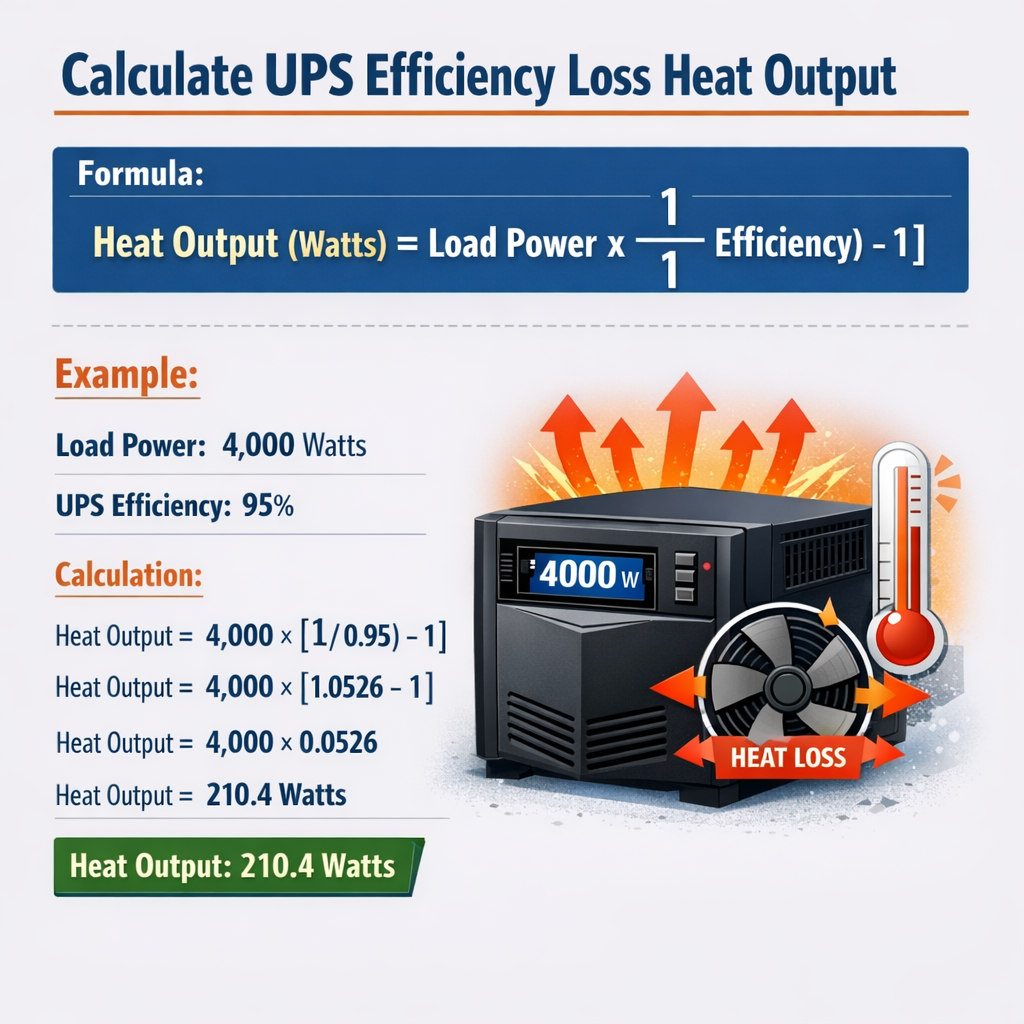
Therefore: Loss (WL) = Pout × (1/η − 1)
Alternative form using efficiency percentage
If η% is efficiency in percent, then: Loss (WL) = Pout × ((100 / η%) − 1)
Variable definitions and typical value ranges
- Pout — Output (load) active power delivered by the UPS, in watts (W). Typical values: 500 W to 1,000,000 W depending on UPS size. Example common ratings: 1 kW, 5 kW, 10 kW, 30 kW, 100 kW.
- Pin — Input active power drawn from the upstream AC source, in watts (W).
- η (eta) — UPS efficiency expressed as fractional (0 to 1). Typical on-line (double-conversion) UPS efficiencies: 0.90–0.97 at rated load depending on design and load. Line-interactive and eco modes may have higher or lower effective efficiencies depending on mode.
- WL — Watts lost inside the UPS. Approximately equal to heat output (W) which must be removed by cooling systems.
- PF — Power factor of the load (unitless, typically 0.8–1.0). When calculating VA and equipment sizing, be careful to convert between VA and W: P (W) = VA × PF.
- Tamb — Ambient temperature. Many UPSes exhibit reduced efficiency at high Tamb due to fan power and thermal derating; typical impact is 0.1–0.5% efficiency loss per 5 °C above nominal.
Component-level loss model and decomposition
For precise thermal accounting you may decompose WL into subcomponents:
- Rectifier/charger losses: conduction and switching losses in the AC-DC stage.
- Inverter losses: conduction and switching losses in the DC-AC stage.
- Transformer losses: core and winding I2R losses (if transformer present).
- Battery charger idle/float losses and battery reconditioning energy.
- Fans and cooling power drawn by the UPS enclosure and internal heat exchangers.
- Control electronics: standby losses from DSPs, display, and monitoring circuits.
- Bypass and static switch losses (if load not fully on inverter or during transfer events).
Component-level measurement is done using power analyzers for each stage, but for most calculations aggregate efficiency curves suffice.
Typical efficiency curves and lookup tables
Different UPS topologies have characteristic efficiency vs. load curves. Use manufacturer data when available; the tables below show representative values used for estimation and planning.
| Technology / Load | 10% Load | 25% Load | 50% Load | 75% Load | 100% Load |
|---|---|---|---|---|---|
| On-line double-conversion (typical modern) | 85%–88% | 90%–92% | 93%–95% | 94%–96% | 95%–97% |
| Line-interactive | 88%–90% | 90%–92% | 92%–94% | 93%–95% | 94%–96% |
| Eco/Bypass mode (when available) | 92%–95% | 95%–97% | 96%–98% | 96%–99% | 97%–99% |
Use the specific product’s efficiency table when available; the above values are illustrative.
Step-by-step procedure to calculate heat output (Watts lost) at any load
- Define the instantaneous real power load Pout (W). If load is specified in VA, convert to W using power factor: Pout (W) = VA × PF.
- Obtain UPS efficiency η for the topology and the load point. Use manufacturer efficiency at the closest percentage load; if unknown interpolate between table points.
- Compute Pin: Pin = Pout / η.
- Compute WL: WL = Pin − Pout = Pout × (1/η − 1).
- Report WL as heat output (W). To convert to thermal units: BTU/h = WL × 3.412142, or kWth = WL / 1000.
- For time-integrated energy: Multiply instantaneous WL by operating time (hours) to obtain Wh or kWh; use this for cooling energy budgeting.
Interpolation method for η at intermediate loads
If manufacturer provides η at discrete points (for example 25%, 50%, 75%, 100%), linearly interpolate in percent-load vs. efficiency space for intermediate loads as a first approximation. For higher accuracy use polynomial regression with manufacturer data points or measure directly with power analyzers.
Tables with computed WL for common UPS sizes
Below are representative computed losses (WL) for several common UPS rated loads using the typical modern on-line efficiency curve shown earlier. Assumptions: efficiency values selected conservatively from the table above: 25%→91%, 50%→94%, 75%→95%, 100%→95.5%. Use the formulas in prior section.
| UPS Rated Output Pout | Load Percent | Pout (W) | Assumed η | Input Pin (W) | Watts Lost WL (W) | BTU/h |
|---|---|---|---|---|---|---|
| 1 kW UPS | 25% | 250 W | 91% | 274.73 W | 24.73 W | 84.4 |
| 1 kW UPS | 50% | 500 W | 94% | 531.91 W | 31.91 W | 108.9 |
| 10 kW UPS | 25% | 2500 W | 91% | 2747.25 W | 247.25 W | 843.6 |
| 10 kW UPS | 50% | 5000 W | 94% | 5319.15 W | 319.15 W | 1089.6 |
| 30 kW UPS | 75% | 22500 W | 95% | 23684.21 W | 1184.21 W | 4040.7 |
| 100 kW UPS | 100% | 100000 W | 95.5% | 104712.04 W | 4712.04 W | 16074.3 |
Worked examples — detailed, step-by-step
Example 1: Small enterprise UPS — 10 kW load at 50% of a 20 kVA UPS
Scenario: A 20 kVA UPS (rated output 20 kVA) is serving a mostly resistive server rack load with PF = 0.9. The instantaneous measured load on the UPS is 10 kW real power. Manufacturer efficiency datasheet indicates η = 93.8% at 50% load. Calculate Watts lost and heat output in BTU/h.
Step 1: Confirm Pout. Given Pout = 10,000 W (already real power).
Step 2: Use given efficiency η = 0.938 (93.8% as a fraction).
Step 3: Compute Pin: Pin = Pout / η = 10,000 W / 0.938 = 10,660.13 W.
Step 4: Compute Watts lost: WL = Pin − Pout = 10,660.13 − 10,000 = 660.13 W.
Step 5: Convert to BTU/h: BTU/h = WL × 3.412142 = 660.13 × 3.412142 ≈ 2252.8 BTU/h.
Result summary:
- Input Power Pin ≈ 10,660 W
- Watts lost WL ≈ 660 W
- Heat output ≈ 2253 BTU/h (≈0.660 kWth)
Notes: If the ambient temperature increases and fan power rises, eta may decline slightly and WL increase by tens to hundreds of watts depending on design.
Example 2: Data center UPS bank — 300 kW IT load at varying load factor
Scenario: A central UPS bank supplies a 300 kW IT load. The UPS manufacturer provides efficiency points: 25%→91.5%, 50%→94.2%, 75%→95.1%, 100%→95.0% (note slight plateau). The data center sometimes runs at 40% load (120 kW). Calculate WL using linear interpolation of efficiency between 25% and 50% points, and compute hourly heat generation if the condition persists for 24 hours.
Step 1: Determine fractional load = 120 kW / 300 kW = 0.40 (40%).
Step 2: Interpolate η between 25% (0.25) at 91.5% and 50% (0.50) at 94.2%.
Linear interpolation formula: η(0.40) = η25 + ( (0.40 − 0.25) / (0.50 − 0.25) ) × (η50 − η25).
Compute fraction = (0.40 − 0.25) / 0.25 = 0.15 / 0.25 = 0.6.
Compute η = 0.915 + 0.6 × (0.942 − 0.915) = 0.915 + 0.6 × 0.027 = 0.915 + 0.0162 = 0.9312 (93.12%).
Step 3: Compute Pin: Pin = 120,000 W / 0.9312 = 128,898 W.
Step 4: Compute WL: WL = 128,898 − 120,000 = 8,898 W.
Step 5: Hourly heat energy: 8,898 W × 1 h = 8.898 kWh per hour. Over 24 hours: 8.898 × 24 = 213.55 kWh.
Step 6: Convert to BTU/h for cooling specification: BTU/h = 8,898 × 3.412142 ≈ 30,368 BTU/h. For 24 hours the total is 30,368 × 24 = 728,832 BTU.
Result summary:
- Interpolated efficiency η ≈ 93.12%
- Watts lost WL ≈ 8,898 W (≈8.9 kW)
- Thermal load for HVAC ≈ 30,368 BTU/h
- Energy dissipated over 24 hours ≈ 213.55 kWh
Practical considerations and corrections
These calculations assume steady-state, real-power conditions and that all electrical losses convert to heat inside or immediately near the UPS bus. In practice:
- Some losses (e.g., battery charging inefficiencies) may be time-dependent and episodic; include charge cycles separately if significant.
- Harmonic currents increase I2R losses and can reduce effective efficiency; use true-power measurements (kW) rather than VA unless PF adjustments are applied.
- Fan power scales with ambient temperature and loading on the UPS; at high ambient, expect an incremental WL due to increased fan energy and reduced converter cooling performance.
- Auxiliary systems (external chillers, ductwork) influence overall site thermal accounting but are not part of the UPS internal WL; however their energy must be included in facility-level energy balances.
- Transient events (transfer, overload, battery discharge) can temporarily change efficiency and losses — account for duty cycles when integrating over time.
Measurement and validation best practices
- Use calibrated true-RMS power analyzers on both UPS input and output circuits to measure Pin and Pout concurrently. Compute η = Pout / Pin directly.
- When measuring Pout, capture real power (W) not apparent power (VA). If only VA is available, apply PF measured at the same time.
- Log data over representative intervals (minutes to hours) to capture variability. For billing-grade or compliance measurement, follow IEC/ISO instrumentation guidance and calibration intervals.
- Isolate the UPS from other loads when performing component-level measurements (e.g., test inverter-only losses by using a controlled resistive load and bypass disabled).
- Apply temperature corrections if manufacturer provides temperature-dependent efficiency correction factors.
Converting losses to cooling requirements and cost
For HVAC sizing, WL (W) is the steady convective+conductive heat the cooling system must remove. Convert WL to common units:
- kWth = WL / 1000
- BTU/h = WL × 3.412142
To estimate cooling energy or cost:
- Cooling electrical demand is facility-specific. Use chiller and CRAH COP/EER: Cooling electrical demand (kW_e) = WL / COP_chiller (for chilled water) plus fan and pump losses.
- Estimate operating cost: Cost = (WL_kW × cooling multiplier × hours × tariff). The cooling multiplier accounts for cooling system efficiency (for example COP = 3 means 1 kWth removal uses ≈0.333 kW_e).
Standards, normative references and authoritative resources
When performing formal measurements, compliance, or reporting, consult the relevant standards and authoritative technical resources:
- IEC 62040 series — Uninterruptible power systems (UPS) standards; particularly IEC 62040-3 for performance and test methods. https://www.iec.ch/
- EN 62040-3 — European adoption of the same performance and test requirements (CENELEC / ETSI repositories).
- IEEE standards and guides related to power quality and power system equipment. See IEEE Power & Energy Society resources: https://pes.ieee.org/
- ASHRAE Datacom series and TC 9.9 — guidance on heat removal and environmental conditions for data centers: https://www.ashrae.org/
- Manufacturer technical papers and whitepapers describing efficiency curves and measurement methods (e.g., Eaton, Schneider Electric, Vertiv). Use manufacturer specification sheets for model-specific efficiency data: https://www.eaton.com/ and https://www.se.com/
- U.S. Department of Energy (DOE) and energy-efficiency programs provide guidance on UPS and data center efficiency measures. DOE reports and calculators can provide site-level context: https://www.energy.gov/
Advanced topics and refinements
For high-accuracy modeling and large installations consider these extensions:
- Dynamic efficiency modeling that includes switching losses vs. load, conduction loss curves, and thermal resistance of components.
- Multi-block UPS banks with circulating currents and load-sharing inefficiencies; include paralleling efficiency penalties.
- Harmonics and total harmonic distortion (THD) impact: model additional I2R losses in transformers and feeders due to non-sinusoidal currents.
- Battery and charger cycling losses: include charge/discharge inefficiencies (round-trip efficiency) when battery operation is frequent.
- Model site-level energy flow: integrate UPS losses with cooling plant efficiency to compute facility PUE-like metrics driven by UPS behavior.
Checklist for practical deployment and reporting
- Record nameplate and rated values: UPS kVA/kW rating, PF rating, and manufacturer efficiency table.
- Measure actual Pout with a calibrated meter; do not rely solely on UPS display if high accuracy is required.
- Use manufacturer curves to estimate η at operating point; interpolate if necessary.
- Compute WL using WL = Pout × (1/η − 1).
- Convert WL to kWth and BTU/h for HVAC sizing; compute kWh if integrating over time.
- Document ambient conditions, PF, THD, and measurement uncertainty for auditability.
Examples of typical pitfalls and how to avoid them
- Using nominal rated efficiency instead of load-specific efficiency — leads to under/over estimation. Always use load-point efficiency.
- Confusing VA and W — always use real power (W) for WL calculations.
- Neglecting auxiliary losses — include fans, control electronics, and charger losses for complete thermal load.
- Failing to account for parallel inefficiencies in multi-module systems — measure the bank, not an individual module.
Quick-reference formulas and unit conversions
Efficiency (fractional): η = Pout / Pin
Loss (Watts): WL = Pout × (1 / η − 1)
Input Power: Pin = Pout / η
kWth: kWth = WL / 1000
BTU/h: BTU/h = WL × 3.412142
Energy over time (kWh): kWh = WL (kW) × operating_hours
Final recommendations for energy efficiency and thermal planning
- Optimize UPS loading: Many modern UPSes have maximum efficiency at or near rated load; operate closer to the efficiency sweet-spot when possible.
- Consider eco or bypass modes for non-critical loads during stable grid conditions to reduce WL if acceptable for reliability strategy.
- Use high-efficiency UPS architectures and energy-saving features (transformerless designs, advanced cooling controls).
- Integrate UPS loss calculations into data center cooling and energy management systems for continuous optimization.
Additional authoritative reading
- IEC 62040-3: Uninterruptible Power Systems (UPS) — Performance and test methods (purchase/standard body overview): https://www.iec.ch/
- ASHRAE Datacom Publications: Environmental standards for data center cooling and heat loads: https://www.ashrae.org/
- US DOE Better Buildings and data center energy efficiency guidance: https://www.energy.gov/
- Manufacturer technical whitepapers on UPS efficiency (examples): Eaton UPS efficiency, Schneider Electric UPS efficiency guides: https://www.eaton.com/ and https://www.se.com/
The methods above enable precise calculation of UPS electrical losses and resulting thermal output at any instantaneous load. For project-level accuracy, corroborate estimates with onsite instrumented measurements and use manufacturer curves where available.