This article presents a rapid method to calculate reduced arcing current accurately and efficiently now.
Engineers will apply calculations, device curves, and system data to ensure protective device sensitivity quickly.Reduced Arcing Current Calculator for Arc-Flash Sensitivity Check (kA)
Scope and applicability
This technical guide describes a rapid, standards-aligned workflow to calculate reduced arcing current after adding impedance or current-limiting elements, and to verify protective device sensitivity. It applies to industrial low-voltage and medium-voltage installations where arc flash risk reduction is sought by changing system impedance, adding reactors, current-limiting fuses, or modifying device settings.Key objectives:- Provide step-by-step calculations to obtain reduced arcing current in minutes.
- Explain formulas, variables, and typical values for practical engineering use.
- Demonstrate verification of protective device sensitivity versus reduced arc current.
- Reference normative standards and authoritative external resources.
Regulatory and standards context
Compliance with arc flash assessment practice is governed by several international and national standards. Use these references for exact procedures and legally binding requirements in your jurisdiction:- IEEE 1584-2018: Guide for Performing Arc-Flash Hazard Calculations — primary methodology for arcing fault calculations. https://standards.ieee.org/standard/1584-2018.html
- NFPA 70E (latest edition): Standard for Electrical Safety in the Workplace — hazard risk categories, PPE selection, and safe work practices. https://www.nfpa.org/70E
- IEC 61482 series: Protective clothing against the thermal hazards of an electric arc — relevant for PPE and test methods. https://www.iso.org/standard/43790.html (IEC reference)
- IEC 60909 / IEEE device coordination guides: For fault current calculations and device coordination principles.
Overview of approach
The rapid method follows these practical steps:- Collect system parameters: nominal voltage, available bolted fault impedance ZS, source short-circuit MVA or available fault currents, conductor configuration, gap, and enclosure type.
- Calculate initial bolted fault current Ibf.
- Apply IEEE 1584 or empirical arcing current factor to estimate initial arcing current Iarc.
- Model mitigation: add series impedance or current-limiting device; compute new bolted fault current Ibf,mit.
- Estimate reduced arcing current Iarc,mit using the same arcing model.
- Verify protective device sensitivity by comparing Iarc,mit to device pickup and trip curves, and calculate clearing times and energy let-through.
- Iterate settings or mitigation until device sensitivity and arc-flash energy targets are met.
Essential formulas and variable definitions
Below are the core formulas used in rapid calculations. Each formula is followed by variable explanations and typical values.1. Bolted fault current (three-phase symmetrical):
Ibf = VLL / (√3 × ZS)
- VLL: Line-to-line nominal voltage (V). Typical values: 480 V, 600 V, 7.2 kV, 13.8 kV.
- ZS: System equivalent impedance seen at the point of fault (Ω). Typical low-voltage loop impedances range from 0.001 Ω to 0.05 Ω depending on source and equipment.
- Ibf: Bolted fault current (A).
2. Reduced bolted fault after series impedance or current-limiter:
Ibf,mit = VLL / (√3 × (ZS + Zseries))
- Zseries: Added series impedance (Ω) from reactors, current-limiting devices, or conductors.
- When using current-limiting fuses or power-limiting devices, model the device as an equivalent time-dependent impedance or use manufacturer I–t / let-through characteristics to determine effective steady-state limiting.
3. Empirical arcing current estimation (simplified factor method):
Iarc = k × Ibf
- k: Arcing factor dependent on voltage, electrode gap, and enclosure. Typical k values (low-voltage): 0.25–0.6; for medium voltage k increases with higher voltage and larger gaps.
- This simplified relation is an expedient engineering approximation when a full IEEE 1584 calculation cannot be performed quickly.
4. Estimated arc incident energy scaling by current:
E ∝ Iarc2 × tclear / dn
- E: Incident energy (cal/cm²).
- Iarc: Arcing current (A).
- tclear: Clearing time (s) — time until device reduces the arc current (operate + arcing duration).
- d: Working distance (mm or inches); exponent n depends on model (IEEE 1584 uses empirically derived relationships).
- Use IEEE 1584 formulas or software to compute accurate incident energy; here the proportionality highlights sensitivity to current and clearing time.
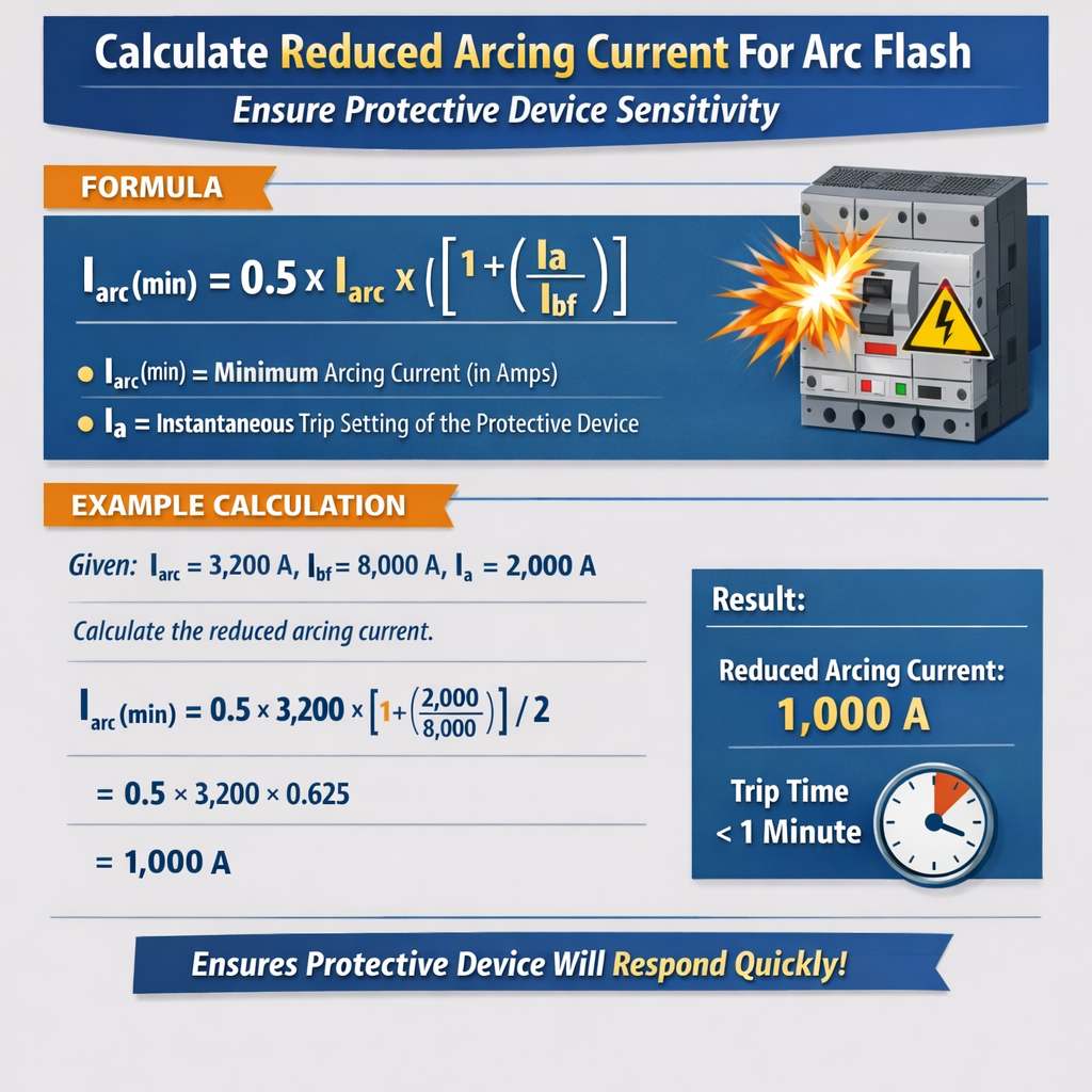
5. Device sensitivity check (instantaneous trip comparison):
Device trips if Iarc,mit ≥ Iinst,set where Iinst,set is instantaneous trip threshold.
- Iinst,set = multiplier × Idevice (device rated current). Example: a circuit breaker with 8× instantaneous pickup means Iinst,set = 8 × Idevice.
- If Iarc,mit < Iinst,set, the device may not operate instantaneously and may have a longer clearing time determined by thermal or long-time curve.
Typical parameters and conversion tables
| Nominal Voltage (V) | Typical k (arcing factor) | Typical Bolted Fault Range (kA) | Typical Arcing Current Range (kA) |
|---|---|---|---|
| 480 | 0.25 – 0.45 | 5 – 50 | 1.25 – 22.5 |
| 600 | 0.28 – 0.48 | 5 – 60 | 1.4 – 28.8 |
| 4.16 kV | 0.4 – 0.8 | 2 – 30 | 0.8 – 24 |
| 13.8 kV | 0.6 – 1.2 | 1 – 20 | 0.6 – 24 |
| Device Type | Common Rating (A) | Typical Instantaneous Multiplier | Typical Clearing Behavior |
|---|---|---|---|
| Molded Case Breaker | 100 – 1200 | 5 – 10× | Instantaneous trip if threshold exceeded; otherwise thermal/long-time trip. |
| Air Circuit Breaker (ACB) | 800 – 6000 | 3 – 10× | Phase instantaneous + time delay; adjustable electronic trip units. |
| Fuse (current-limiting) | 100 – 4000 | Not applicable | Fast clearing; strong current limiting and low I^2t let-through. |
| Series Reactor | — | — | Acts as impedance; reduces steady-state and peak fault currents. |
Using manufacturer data for current-limiting devices
When current-limiting fuses or electronic limiters are deployed, do not simply model them as a static Z. Instead:- Obtain I–t curves and let-through I^2t tables from manufacturer datasheets.
- Estimate the effective maximum arcing current during the arcing interval based on the device's limiting performance.
- Where required, perform a time-domain simulation or use vendor software, especially for fast transients and medium-voltage devices.
Step-by-step rapid calculation workflow (practical)
Use this checklist to perform a quick field or desktop calculation in minutes:- Collect essential data:
- Nominal system voltage VLL.
- Available bolted fault current Ibf or source impedance ZS at the equipment terminal.
- Equipment enclosure type, electrode configuration, and electrode gap (for IEEE 1584 accuracy).
- Protective device type, rating, and trip settings (instantaneous multiplier, long-time pickup, time dial).
- Any added impedance or devices (reactor inductance L or Zseries, fuse data).
- Calculate Ibf if only ZS known:
Ibf = VLL / (√3 × ZS)
- Estimate initial Iarc:
Iarc = k × Ibf (select k from table based on voltage and gap)
- Model mitigation:
Ibf,mit = VLL / (√3 × (ZS + Zseries))
Iarc,mit = k × Ibf,mit (or use device let-through data for fuses)
- Check protective device sensitivity:
- Is Iarc,mit ≥ Iinst,set? If yes, instantaneous trip will likely clear rapidly.
- If not, determine clearing time using the breaker’s time-current curve at Iarc,mit.
- Compute approximate arc energy: E ≈ C × Iarc,mit2 × tclear (C is calibration factor based on distance/enclosure); use IEEE 1584 or software for precise energy.
- Iterate settings or mitigation until arc energy or required clearing times are achieved while maintaining selectivity and coordination.
Example 1 — Low-voltage MCC feeder with added series reactor
Scenario summary:- System: 480 V three-phase, solidly connected utility source.
- Original measured bolted fault current at motor control center (MCC) bus: Ibf = 20 kA.
- Protective device: Molded case breaker (MCB) rated 1200 A with instantaneous multiplier 8× (Iinst,set = 9600 A).
- Objective: Reduce arcing current so device operates instantaneously or reduce incident energy to below specified PPE level.
- Mitigation chosen: 0.02 Ω series reactor installed in the feeder.
Select k for 480 V enclosed bus, typical k = 0.35.
Iarc = k × Ibf = 0.35 × 20,000 A = 7,000 A.
Step 2 — device instantaneous check (before mitigation):Iinst,set = 8 × 1200 A = 9,600 A.
Since Iarc = 7,000 A < 9,600 A, the MCB will not trip instantaneously on arcing current; clearing time will follow time-delay curve.
Step 3 — compute new bolted fault with series reactor:Find equivalent ZS from original Ibf:
ZS = VLL / (√3 × Ibf) = 480 / (√3 × 20,000) ≈ 0.0139 Ω.
Add Zseries = 0.02 Ω => Ztotal = 0.0339 Ω.
Ibf,mit = 480 / (√3 × 0.0339) ≈ 8,180 A.
Step 4 — estimate reduced arcing current:Iarc,mit = k × Ibf,mit = 0.35 × 8,180 A ≈ 2,863 A.
Step 5 — device sensitivity check after mitigation:Iinst,set = 9,600 A (unchanged). Now Iarc,mit = 2,863 A < 9,600 A, still below instantaneous threshold.
However, because bolted fault reduced to 8.18 kA, the breaker’s time-current curve at 2.863 kA will operate on long-time/short-time elements, leading to substantially longer clearing time than instantaneous.
Step 6 — compute approximate clearing time and energy (basic estimation):Assume breaker long-time / short-time settings produce clearing at 0.5 s for this current (consult manufacturer curve for precise number).
Approximate energy proportionality: E ∝ Iarc,mit2 × t = (2,863)2 × 0.5 ≈ 4.1×10⁶ A2s (relative metric).
Compare to original: original energy ~ (7,000)2 × 0.5 = 24.5×10⁶ A2s — energy reduced by ≈83%.
Interpretation:- Series reactor significantly reduces both bolted fault and arcing current.
- Device still may not trip instantaneously, but total incident energy reduced markedly due to lower current squared effect.
- For PPE determination and final verification, calculate incident energy using IEEE 1584 or software with the new Iarc,mit and actual clearing time.
Example 2 — 5 kV medium-voltage switchgear with current-limiting fuse
Scenario summary:- System: 5 kV medium-voltage feeder; measured available bolted fault current at switchgear bus: Ibf = 10 kA.
- Protective device: Victim device is a downstream vacuum circuit breaker with instantaneous multiplier 6× (Iinst,set = 6 × rated current). Breaker rated 2000 A, so Iinst,set = 12,000 A.
- Mitigation: Install current-limiting fuses on the feeder optimized to limit prospective fault to a peak of 6 kA during arcing time interval.
- Electrode gap and enclosure: switchgear with internal arc gap, typical medium-voltage k = 0.7.
k = 0.7; Iarc = 0.7 × 10,000 A = 7,000 A.
Iinst,set = 12,000 A so baseline arcing current would not trigger instantaneous trip.
Step 2 — apply fuse limiting (manufacturer data):Manufacturer states that with the selected fuse, typical peak during a bolted fault is limited to 6 kA and arcing current will not exceed this peak during the fuse clearing interval.
Therefore use Ibf,mit ≈ 6,000 A in subsequent arcing estimate.
Step 3 — estimate reduced arcing current using k:Iarc,mit = 0.7 × 6,000 A = 4,200 A.
Step 4 — verify device sensitivity:Iinst,set = 12,000 A > Iarc,mit = 4,200 A — breaker still will not trip instantaneously.
But because fuse is current-limiting and opens within a few cycles (typically 3–6 cycles), the clearing time is small (t < 0.1 s), drastically reducing arc energy.
Step 5 — compute relative energy reduction:Approximate energy: E ∝ Iarc,mit2 × t ≈ (4,200)2 × 0.08 s ≈ 1.4×10⁶ A2s.
Compare to baseline: (7,000)2 × 0.5 s ≈ 24.5×10⁶ A2s. Energy potentially reduced by >95% depending on assumed clearing times.
Interpretation:- Current-limiting fuse achieves both lower arcing current and very short clearing time, dramatically reducing incident energy.
- Breaker instantaneous pickup remains above reduced arc current, but clearance is achieved by the fuse instead of the breaker; coordination must be checked to ensure fuse clears before breaker attempts to trip.
Practical verification with device time-current curves
To ensure the protective device is sensitive to the reduced arcing current in the intended timeframe, perform the following verifications:- Plot Iarc,mit on the device time-current curves (manufacturer data) to determine estimated clearing time tclear. For breakers, read time at that current on the curve; for fuses, use I–t manufacturer data or let-through tables.
- Compute arc energy using IEEE 1584 or software using Iarc,mit, tclear, working distance, and enclosure factors to obtain incident energy in cal/cm².
- Confirm incident energy meets desired safety limits or PPE categories; if not, iterate by adjusting series impedance, device settings (lower instantaneous or short-time pickup if feasible), or deploying additional mitigation like zone-selective interlocking.
Checklist for quick field decision-making
- Is the measured or calculated bolted fault current credible? Validate using utility or transformer MVA data.
- Has the arcing factor k been chosen conservatively for the equipment and configuration?
- Does added impedance reduce Ibf enough to reduce Iarc below device instantaneous threshold if that is required?
- If device does not trip instantaneously at Iarc,mit, is the resulting clearing time acceptable for incident energy goals?
- Are coordination and selectivity preserved after mitigation to prevent unwanted upstream trips?
Notes on accuracy and limitations
- The simplified factor method (Iarc = k × Ibf) is intended for rapid engineering assessments. Use IEEE 1584 calculations or accredited software for final designs, PPE selection, or legal compliance.
- Medium- and high-voltage systems often require dynamic modeling and manufacturer cooperation for current-limiting devices. Time-domain simulations may be necessary.
- Series impedance from conductors may be frequency dependent; for transients, inductance matters. For steady-state bolted fault estimates, the R and X components should be used to find |Z|.
Recommended tools and resources
Use professional tools for precision and reporting:- IEEE 1584-compliant arc flash calculators (vendor tools often embedded in SKM PowerTools, ETAP, EasyPower).
- Short-circuit software for accurate ZS extraction and fault current distribution.
- Manufacturer protection coordination software for plotting device curves and verifying clearing times.
References and authoritative links
- IEEE Std 1584-2018, Guide for Performing Arc-Flash Hazard Calculations — detailed methodology, empirical coefficients, and enclosure/gap models. https://standards.ieee.org/standard/1584-2018.html
- NFPA 70E — Electrical Safety in the Workplace — hazard assessment and PPE requirements. https://www.nfpa.org/70E
- IEC 61482 (parts) — Protective clothing against thermal hazards of electric arc. https://www.iso.org/standard/43790.html (IEC/ISO cross-reference)
- Manufacturer protection data: ABB, Siemens, Schneider Electric, Eaton — consult device manuals and I–t curves for accurate coordination.
- IEEE PES resources and tutorials on arc flash boundary and mitigation strategies. https://pes.org