Star-delta starting calculators streamline three-phase motor starting computations for engineers and field technicians in industry.
This effortless tool reduces downtime, ensures accurate torque and current estimates, and aids compliance rapidly.Star-Delta Starting Calculator — Technical Effortless Tool
Star‑Delta Starting Fundamentals and Practical Importance
Star‑delta (Y‑Δ) starting is a reduced‑voltage method used to limit inrush currents and torque during induction motor start-up. It temporarily connects the stator windings in star (Y) during acceleration and then transfers to delta (Δ) for normal running. The technique reduces the line current and starting torque to approximately one third (1/3) of the direct‑online (DOL) values when switching is ideal.
When and why engineers choose star‑delta starting
- Large motors where DOL starting causes unacceptable voltage dips on the supply network.
- Applications that tolerate reduced starting torque (pumps, fans, light conveyors).
- To reduce required size and cost of upstream switchgear, fuses, and cabling compared with DOL.
- Legacy systems and simple control schemes where inverter solutions are not cost‑effective.
Core Electrical Relationships for Star and Delta Connections
The key to any calculator is correct electrical relationships between phase and line voltages, currents, and torque. Below are compact, usable formulas (plain text / character math):
Phase and line voltages:
Phase and line currents (definitions):
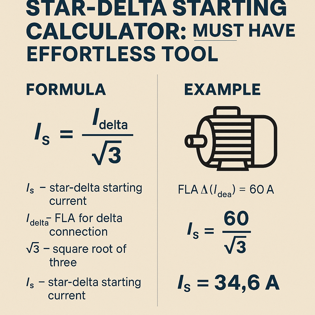
Relating star current to delta current (starting current ratio):
Torque proportionality (approximate below base speed):
Torque ∝ V_ph^2
Variable definitions and typical values
- V_line — Line (line‑to‑line) supply voltage, e.g., 400 V (Europe), 480 V (North America), 600 V.
- V_ph_delta — Phase voltage when windings in delta; equals V_line.
- V_ph_star — Phase voltage when windings in star; equals V_line / √3.
- I_ph — Phase current through an individual winding.
- I_line — Line current delivered by supply conductors.
- I_FL — Rated full load current from motor nameplate (A).
- I_LR — Locked‑rotor or starting current in delta connection; typically 4–8 × I_FL (use nameplate if available).
- T — Torque; starting torque in star ≈ 1/3 of starting torque in delta.
Calculator Design: Inputs, Outputs, and Assumptions
A robust star‑delta starting calculator should accept these inputs and provide required outputs:
- Inputs:
- Motor rated power (kW or HP)
- Rated voltage (V_line) and frequency (Hz)
- Rated full load current (I_FL) or nameplate data
- Locked rotor multiplier (typical 4–8 × I_FL) if nameplate LRA unknown
- Start time (seconds), load torque requirement at start
- Outputs:
- Estimated DOL starting current (I_LR) and star starting current (I_star)
- Estimated starting torque in star and delta
- Recommended contactor and fuse sizes (multiples of I_FL), cable sizing guidance
- Energy / thermal equivalent during start to guide thermal overload settings
- Assumptions:
- Motor behaves linearly with applied phase voltage for current and torque proportionalities at low speed.
- Supply remains stiff; voltage drop effects on network not modeled explicitly unless network impedance provided.
Key Formulas — presented with plain characters
Full set of working formulas that a calculator implements:
1) Convert motor power to current (approximate for three‑phase induction motor):
Typical PF = 0.85–0.95, Efficiency = 0.85–0.95 (use nameplate for accuracy).
2) Estimate locked rotor current (delta / DOL) if not specified:
I_LR_delta ≈ K_lr × I_FL
Typical K_lr = 4 to 8 (manufacturers provide locked rotor current on nameplates).
3) Star starting line current:
4) Starting torque relationship:
5) Thermal equivalent during start (simplified):
Energy_eq ≈ ∫ I^2 dt over starting interval ≈ I_rms^2 × t_start (for immediate estimate)
6) Contactor selection guidance:
Select contactor rated for at least continuous I_FL and inrush capacity for switching. Use thermal and mechanical ratings as per IEC 60947‑4‑1.
Explanation of variables and typical numeric ranges
- P_kW — motor power in kilowatts (typical industrial motors: 0.75 kW to 1000 kW).
- V_line — supply voltage (e.g., 400 V, 415 V, 480 V, 600 V).
- PF — power factor at full load (0.75 to 0.95 typical depending on size and load).
- Efficiency — mechanical to electrical efficiency (0.7 to 0.98 depending on motor class and size).
- I_FL — rated full load current (A) — use nameplate if present.
- t_start — start time in seconds (commonly 1–20 s depending on load).
- I_rms — RMS current during start; numeric estimation depends on start profile and switching instant.
Tables of Typical Values and Conversion Factors
| Motor Power (kW) | Approx. Full Load Current at 400 V (A) | Typical Locked Rotor Multiplier (K_lr) | Estimated DOL Starting Current (I_LR, A) | Estimated Star Starting Current (I_star ≈ I_LR/3, A) |
|---|---|---|---|---|
| 1.1 | 2.3 | 5 | 11.5 | 3.8 |
| 3.0 | 5.4 | 5 | 27.0 | 9.0 |
| 7.5 | 13.4 | 6 | 80.4 | 26.8 |
| 11.0 | 20.0 | 6 | 120.0 | 40.0 |
| 22.0 | 39.0 | 6 | 234.0 | 78.0 |
| 55.0 | 95.0 | 6 | 570.0 | 190.0 |
| Voltage Standard | V_line (nominal) | V_ph (delta) | V_ph (star) | Star/Delta Current Ratio |
|---|---|---|---|---|
| European 400 V 50 Hz | 400 V | 400 V | 231 V | 1 : 3 |
| North America 480 V 60 Hz | 480 V | 480 V | 277 V | 1 : 3 |
| 600 V 60 Hz | 600 V | 600 V | 346 V | 1 : 3 |
| Motor Size | Typical Starting Torque (Δ) | Typical Starting Torque (Y) | Usable Application Examples |
|---|---|---|---|
| 0.75–3 kW | 2–3 × T_nom | 0.67–1 × T_nom | Small pumps, fans, mixers |
| 4–30 kW | 3–5 × T_nom | 1–1.7 × T_nom | Medium fans, conveyor belts |
| 30–200 kW | 4–6 × T_nom | 1.3–2 × T_nom | Large pumps, compressors (light loads) |
Worked Example 1 — 55 kW Motor, 400 V, 50 Hz (Typical Industrial Case)
Problem statement: A 55 kW squirrel‑cage induction motor operates from a 400 V, 50 Hz supply. Nameplate shows full load current I_FL = 95 A and locked rotor current I_LR (delta) = 6.0 × I_FL. The load is a centrifugal pump requiring low starting torque. Determine star starting current, starting torque ratio, and recommended contactor sizing for star and delta stages. Also estimate thermal energy during a 6 s start.
Step 1 — Known values
- P = 55 kW
- V_line = 400 V
- I_FL = 95 A (from nameplate)
- K_lr = 6.0 → I_LR_delta = 6 × 95 = 570 A
- Start duration t_start = 6 s
Step 2 — Star starting current
Apply the 1/3 ratio:
Step 3 — Starting torque estimate
Starting torque in delta T_delta proportional to spin‑up torque (use nameplate locked torque if provided). If T_delta is unknown, use ratio:
Interpretation: Star starting torque should be approximately one third of delta starting torque; for a pump this is often acceptable because torque demand at start is low.
Step 4 — Thermal energy estimate during start
Simplified I^2t energy metric (approximate):
Energy_eq ≈ I_rms^2 × t_start
Assume current during star start approximates starting current value 190 A RMS for 6 s:
Note: For thermal protection, compare this to manufacturer thermal trip curves or convert to A^2s rating of overload relay.
Step 5 — Contactor and fuse selection guidance
- Star contactor must safely carry star starting current 190 A during start and continuous I_FL 95 A. Choose a contactor rated for at least 200 A making capacity and appropriate duty (verify manufacturer data sheets).
- Delta contactor must make at switching instant at the end of star period — it must withstand inrush of I_line_delta = 570 A (make capacity), brief current peaks, and continuous 95 A running current. Use contactors with adequate mechanical breaking and making ratings (see IEC 60947‑4‑1).
- Fuses upstream sized for coordination: consider using time‑delay fuses rated slightly above 95 A for running and verify fault clearing capability. Coordination with star/delta switches recommended.
Interpretation
Using star gives a controlled reduced starting current (190 A vs 570 A) and reduced mechanical stress. The delta contactor must be rated to close under larger inrush. Protection and interlocking are required to avoid closing delta while a winding remains connected to star.
Worked Example 2 — 11 kW Motor, 480 V, 60 Hz (North American Application)
Problem statement: A factory uses an 11 kW, 480 V, 60 Hz motor driving a conveyor. Nameplate I_FL = 20 A, locked rotor current unknown. The start must limit line current because supply transformer rating is constrained. Estimate starting currents, verify if star starting suffices, and suggest contactor and overload relay settings.
Step 1 — Known and assumed values
- P = 11 kW
- V_line = 480 V
- I_FL = 20 A (nameplate)
- Assume K_lr = 6 (typical) → I_LR_delta ≈ 6 × 20 A = 120 A
- Star starting current I_line_star = 120 / 3 = 40 A
Step 2 — Evaluate against supply constraints
If transformer secondary can supply a maximum continuous 60 A without harmful voltage drop, DOL starting at 120 A could cause excessive voltage sag. Star starting at 40 A is within acceptable limits and reduces electrical impact.
Step 3 — Verify starting torque requirements
Assume Δ starting torque T_delta sufficiently greater than required starting torque of conveyor; star torque is ~1/3 T_delta. If conveyor requires torque < 1/3 T_delta, star is acceptable. Determine required torque from mechanical design (mass, friction, slope).
Step 4 — Protection and settings
- Overload relay should be set to 20 A (I_FL) for long term protection.
- Star contactor must carry 40 A during start and continuous 20 A running.
- Delta contactor must make at 120 A (closing from star to delta); ensure contactor make ratings and mechanical interlocks are correct per IEC 60947.
Step 5 — Timing strategy
Typical timers: 1–3 s for light load; longer for heavy loads. The calculator should allow trial of 1, 3, 6, and 10 s start times and compute energy_eq to verify thermal protection coordination.
Implementation Considerations and Best Practices
- Sequence and interlocks: Implement mechanical and electrical interlocks to prevent simultaneous star and delta contactor closure. Use an accurate timing relay or PLC logic ensuring dead time between contactor transitions.
- Switching under torque: Avoid closing delta contactor while the motor draws large differential currents. Some systems use slip‑ring resistors or controlled timers based on motor current decay.
- Monitoring: Include current measurement (CTs) to verify actual starting current and to detect failed transitions (e.g., stuck in star).
- Maintenance: Periodically inspect contactor contacts for welding, measure resistance of contactors and transition timing to check correct operation.
- Start attempts: Provide anti‑restarting logic if repeated unsuccessful starts occur to protect against thermal accumulation.
Control diagram essentials (logical)
- Start command → energize star contactor and main contactor (if separate) and timer.
- Timer elapsed → de‑energize star contactor → short dead time (50–200 ms) to avoid cross conduction.
- After dead time → energize delta contactor for run.
- Stop command → de‑energize contactors in sequence to break current safely.
Protection, Sizing and Coordination Rules
- Use nameplate I_FL for cable sizing and overload relay thermal settings. Continuous cable rating should exceed I_FL and consider ambient, grouping, and derating factors.
- Fuses and MCCB settings must coordinate with motor starting characteristics. Time‑delay (slow blow) fuses often used to allow high inrush without nuisance blowing.
- Contactors should be rated per manufacturer for making and breaking currents at motor starting conditions; consult IEC 60947‑4‑1 and manufacturer tables.
- Consider supply impedance when estimating actual starting currents — calculators that accept source impedance or transformer X/R ratio improve accuracy.
UX and Calculator Features That Engineers Must Have
An effortless tool should include:
- Clear input fields with units (kW, HP, V, Hz, I_FL, K_lr, PF, Efficiency).
- Option to input nameplate locked‑rotor current for accuracy.
- Pre‑filled typical values and industry presets (e.g., 400 V/50 Hz, 480 V/60 Hz).
- Graphical output: current vs time profile, torque vs time curve, and I^2t energy plot.
- Exportable reports with step‑by‑step calculations and component sizing recommendations.
- Standards references, warnings, and checks (e.g., warn if star torque insufficient).
Standards, Normative References and Further Reading
Relevant standards and authoritative references that support correct design and selection:
- IEC 60034 — Rotating electrical machines (general requirements and ratings). See: https://www.iec.ch
- IEC 60947‑4‑1 — Contactors and motor starters (electromechanical). See: https://www.iec.ch
- IEC 60364 — Electrical installations of buildings (for installation practices).
- NEMA MG1 — Motors and Generators (US authority for motor performance and testing). See: https://www.nema.org
- Manufacturer technical guides (Siemens, ABB, Schneider Electric) on star‑delta starters and contactor selection:
- Siemens motor starters application notes: https://new.siemens.com
- ABB motor starter guides: https://global.abb
- Engineering reference articles:
- EngineeringToolBox — motor current and power conversion charts: https://www.engineeringtoolbox.com
- Technical whitepapers on starting currents and network impacts from utility or motor manufacturers.
Regulatory and safety notes
- Comply with local electrical codes (e.g., NEC in USA, IEC harmonized rules in many countries) for protective device sizing and installations.
- Lockout/tagout and safe access required for commissioning and maintenance.
Practical Summary and Decision Checklist
- Verify motor nameplate data first — use I_FL and locked rotor current when provided.
- If locked rotor current unknown, use conservative K_lr (4–8) based on motor size and construction.
- Confirm required starting torque vs available star torque (≈ 1/3 of delta). If insufficient, consider soft starter or VFD.
- Ensure contactor making ratings, fuse coordination, and control interlocks meet standards (IEC/NEMA).
- Use start timers conservatively and monitor I^2t thermal equivalents to avoid thermal overload nuisance trips.
References and Authoritative Links
- IEC catalog — https://www.iec.ch
- NEMA publications and technical resources — https://www.nema.org/
- Siemens motor starters and starting methods — https://new.siemens.com/global/en/products/drives/motor‑starters.html
- ABB motors and soft starting literature — https://new.abb.com/products/motors‑generators
- EngineeringToolBox (tables and conversions) — https://www.engineeringtoolbox.com/
This article delivers the technical basis and practical steps to build or use a star‑delta starting calculator. Engineers should integrate accurate nameplate data, network impedance where available, and follow local codes during implementation.